
Aircraft having a rear section with a continuous skin for the fuselage and the vertical tail plane

a vertical tail plane and fuselage technology, applied in the rear section of aircraft, can solve the problems of inability to meet the requirements increase the manufacturing cost, and drawback of the main interface fitting b>16/

Inactive Publication Date: 2018-06-21
AIRBUS OPERATIONS SL
View PDF0 Cites 4 Cited by
  • Summary
  • Abstract
  • Description
  • Claims
  • Application Information

AI Technical Summary

Benefits of technology

The invention is an aircraft rear section design that improves load distribution and reduces weight and complexity penalties. It includes a continuous joint between the fuselage and the empennage, as well as a dorsal fin with internal structural components. This design ensures the aircraft can safely continue flight and landing in the event of an engine detachment.

Problems solved by technology

Conventionally these frames are heavy metallic frames as the composite ones are not able to withstand these high punctual loads in a competitive manner.
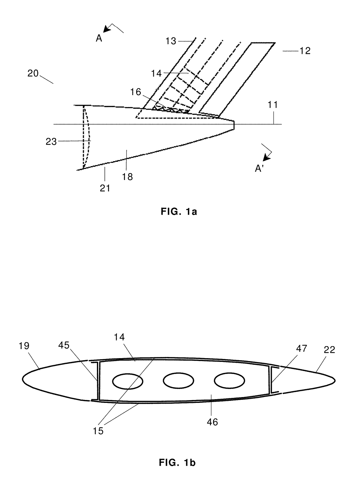
Consequently, the main problem to be improved at the first place is the drawback of the main interface fittings 16.
They also increment the manufacturing cost as they are additional secondary structure that needs to be installed after the vertical tail plane 13 in the final assembly line, increasing the lead time and complexity of this final process.
They are also thin nonstructural components that can be easily damaged during the operation of the aircraft so they need to be replaced or repaired frequently, because they affect the esthetics of the aircraft, impacting its operational cost.
Although several solutions for the main interface fittings 16, the supporting frames 41 and the covering fairings are known, both its weight and high complexity represent drawbacks for the performance, manufacture and operability of the aircraft.
Another problem of aircraft having the above mentioned configuration, when they are provided with a propulsion system in the rear section of the aircraft, is related to failure events such an UERF (“Uncontained Engine Rotor Failure”) event, i.e. an event where a part of the rotors of the gas generator or of the fan of the engine breaks and it is released with high energy and impacts the empennage, fuselage and opposite engine.
This situation is catastrophic as the aircraft is not able to perform safe continuation of flight and landing without this element.
As a result of this structure duplication, there is a weight penalty for the aircraft.
When the engines debris impacts the opposite engine, both engines are lost and the situation is also catastrophic, as the aircraft is not able to perform safe continuation of flight and landing, depending on the flight phase.
In order to reduce the damage on the fuselage and the empennage and to stop the debris before impacting the opposite engine, additional reinforcement and shielding is added to the rear end impacted zones, producing significant additional penalty weight and complexity.
This dorsal fin is an extension of the vertical tail plane structure on its front area, and it is conventionally also attached to the fuselage by discrete fittings covered by fairings, and leading to equivalent drawbacks and weight penalizations as previously described.

Method used


Image

  • Aircraft having a rear section with a continuous skin for the fuselage and the vertical tail plane
  • Aircraft having a rear section with a continuous skin for the fuselage and the vertical tail plane
  • Aircraft having a rear section with a continuous skin for the fuselage and the vertical tail plane

Examples


Embodiment Construction

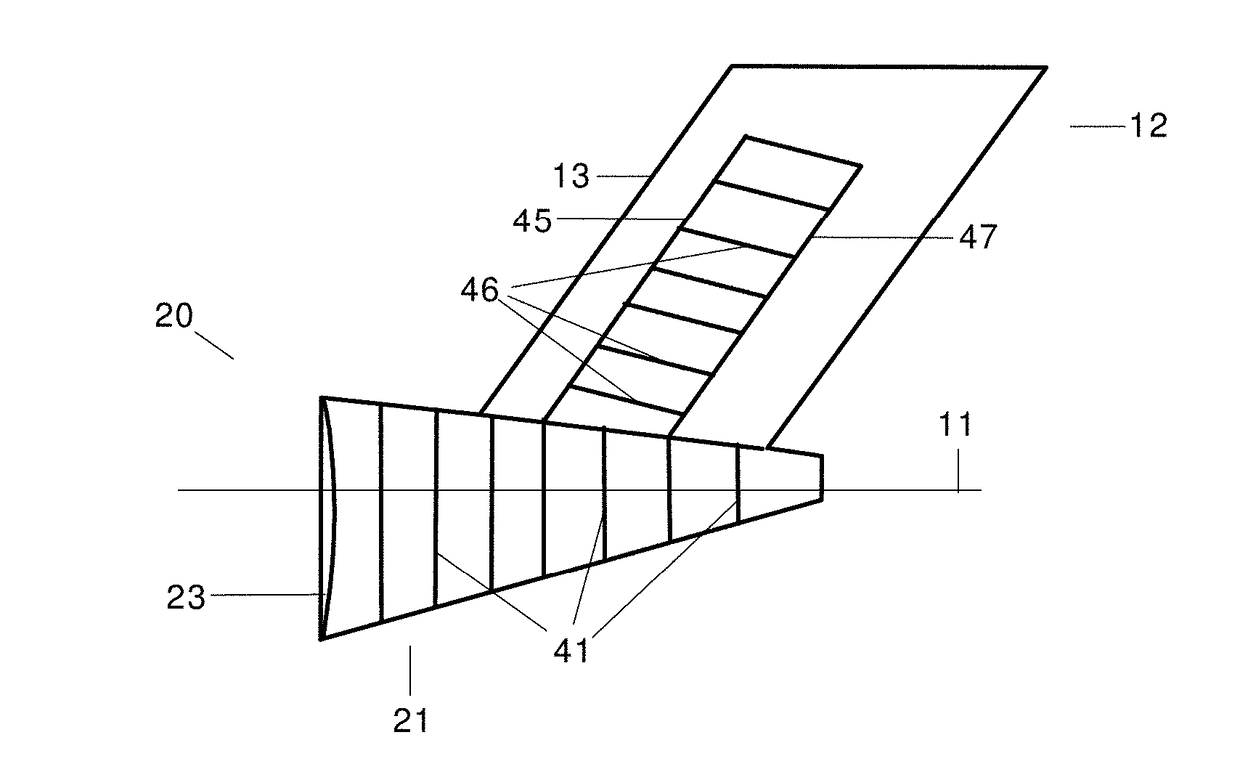
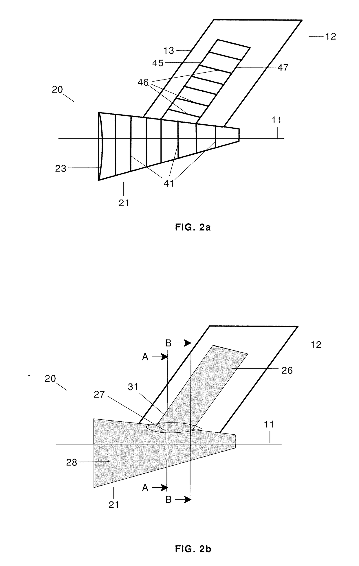
[0069]The main difference between an aircraft according to the invention (see FIGS. 2a and 2b) and the aircraft mentioned in the Background (see FIGS. 1a and 1b) is that the main interface fittings 16 for joining the fuselage rear section 21 and the lateral skins of the torsion box 14 of the vertical tail plane 13 have been eliminated and said junction is accomplished through a continuous skin 31 (formed by two lateral continuous skins placed symmetrically with respect to the middle vertical plane of the aircraft) joined to the inner structural components of the fuselage rear section 21 and of the vertical tail plane 13. Additionally, the fuselage rear section 21 may comprise a top panel 33 for the upper part of the fuselage located in between the lateral sides of the continuous skin 31.

[0070]The internal structure inside the transition and upper parts of the continuous skin 31, between the front and rear spars 45 and 47, may also comprise ribs 46 and intermediate spars (not represe...


PUM


Abstract

An aircraft rear section (20) including a fuselage rear section (21) extending from the rear pressure bulkhead (23) to the end of the fuselage and an empennage (12) including at least a vertical tail plane (13). An aircraft rear section (20) with a continuous skin (31) is formed by two lateral sides placed symmetrically with respect to the middle vertical plane of the aircraft, each side including an upper portion (26) for the torsion box (14) of the vertical tail plane (13), a lower portion (28) for the fuselage rear section (21) and a transition portion (27) between the upper and lower portions (26, 28). The upper and lower portions (26, 28) of the continuous skin (31) are joined to inner structural components of the vertical tail plane (13) and the fuselage rear section (21).

Description

RELATED APPLICATION[0001]This application claims priority to European Patent Application 16382612.6 filed Dec. 16, 2016, the entirety of which is incorporated by reference.FIELD OF THE INVENTION[0002]The present invention relates to a rear section of an aircraft having attached a vertical tail plane and more particularly to a configuration that includes a propulsion system attached to the rear fuselage.BACKGROUND OF THE INVENTION[0003]This invention refers mainly to aircraft having a rear section 20 configured with an empennage 12, comprising a vertical tail plane 13 and an upper horizontal tail plane behind the propulsion system, joined to the fuselage rear section 21 (see FIGS. 1a and 1b).[0004]The vertical tail plane 13 comprises, typically, a leading edge 19, a torsion box 14 and a trailing edge 22. The torsion box 14 comprises front and rear spars 45, 47, ribs 46 and left and right lateral skins 15 stiffened by stringers (not shown in FIGS. 1a and 1b). The torsion box 14 is joi...

Claims


Application Information

Patent Timeline
Patent Type & Authority Applications(United States)
IPC IPC(8): B64C1/26B64C5/02B64C1/06B64D27/14B64D27/20
CPCB64C1/26B64C5/02B64C1/068B64D27/14B64D27/20B64C1/061B64C2001/0072B64C1/069B64C1/12B64C1/0685
Inventor MARTINO GONZ LEZ, ESTEBANFOLCH CORTES, DIEGOPINA LOPEZ, JOSE MARIA
Owner AIRBUS OPERATIONS SL
Learn More