Shower plate structure for exhausting deposition inhibiting gas

a technology of shower plate and inhibiting gas, which is applied in the direction of spray nozzle, coating, basic electric elements, etc., can solve the problems of difficult formation of film with a conventional shower head, negative impact on the uniform deposition of film on the surface of a substrate, etc., and achieve the effect of improving the structure of shower plate and increasing the uniformity of film formed

Active Publication Date: 2018-06-21
ASM IP HLDG BV
View PDF4 Cites 124 Cited by
  • Summary
  • Abstract
  • Description
  • Claims
  • Application Information

AI Technical Summary

Benefits of technology

[0006]In recent years, methods for depositing a film on a patterned surface have been proposed by improving the structure of the shower plate. The demand for forming a film more uniformly on the patterned surface is ever increasing. However, forming a film with a conventional shower head may be difficult. One reason is a problem of by-products remaining between the shower plate structure and the shield plate, e.g., both ends of the gas inlet space and areas around the O-ring 4, which poses a negative impact on uniform deposition of the film on the surface of a substrate. Thus development of the shower head which is capable of exhausting such by-products outside of the shower head and the chamber becomes important to help increase the uniformity of the film formed on the surface of the substrate.

Problems solved by technology

However, forming a film with a conventional shower head may be difficult.
One reason is a problem of by-products remaining between the shower plate structure and the shield plate, e.g., both ends of the gas inlet space and areas around the O-ring 4, which poses a negative impact on uniform deposition of the film on the surface of a substrate.

Method used


Image

  • Shower plate structure for exhausting deposition inhibiting gas
  • Shower plate structure for exhausting deposition inhibiting gas
  • Shower plate structure for exhausting deposition inhibiting gas

Examples


example 1

[0036]Shower plate with a plurality of apertures extending from the surface of the stepped section to the exhaust duct.

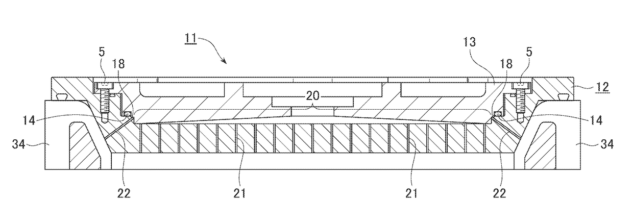
[0037]A schematic view of an embodiment of a shower plate structure with a shield plate (the shower head) is shown in FIG. 3. The shower head 11 has a shower plate structure 12 and a shield plate 13 which partially define a gas inlet space. The shower plate structure 12 and the shield plate 13 are fixed with a screw 5. An O-ring 14 is attached between the shower plate structure 12 and the shield plate 13. The shower plate 12 has a stepped section 18 on the front surface side of the shower plate 12, and a front surface area 20 (a front surface) is surrounded peripherally by the stepped section 18. At least one aperture 22 extends from the surface of the stepped section 18 to the exhaust duct for passing by-product gas therethrough in this direction.

[0038]Configuration of the Aperture 22

[0039]Number of apertures: 96

[0040]Diameter: 1 mm

[0041]Length: 33.88 mm

[0042]Incli...

example 2

[0048]Shower plate with a plurality of apertures extending from the edge of the front surface to the exhaust duct.

[0049]A schematic view of an embodiment of a shower plate structure with a shield plate (the shower head) is shown in FIG. 5. The shower head 11 has a shower plate structure 12 and a shield plate 13 which define a gas inlet space. The shower plate structure 12 and the shield plate 13 are fixed with a screw 5. An O-ring 14 is attached between the shower plate structure 12 and the shield plate 13. The shower plate 12 has a stepped section 18 on the front surface side of the shower plate 12, and a front surface area 20 (a front surface) is surrounded peripherally by the stepped section 18. At least one aperture 23 extends from the edge of the front surface 20 of the shower plate structure 12 to the exhaust duct for passing by-product gas therethrough in this direction.

[0050]Configuration of the Aperture 23

[0051]Number of apertures: 96

[0052]Diameter: 1 mm

[0053]Length: 31.93 ...

example 3

[0060]Shower plate with a plurality of apertures extending from the edge of the front surface of the shower plate to the rear surface thereof.

[0061]A schematic view of an embodiment of a shower plate structure with a shield plate (the shower head) is shown in FIG. 6. The shower head 11 has a shower plate structure 12 and a shield plate 13 which define a gas inlet space. The shower plate structure 12 and the shield plate 13 are fixed with a screw 5. An O-ring 14 is attached between the shower plate structure 12 and the shield plate 13. The shower plate 12 has a stepped section 18 on the front surface side of the shower plate 12, and a front surface area 20 (a front surface) is surrounded peripherally by a stepped section 18. At least one aperture 24 extends from the edge of the front surface 20 of the shower plate 12 to the rear surface 30 of the shower plate 12.

[0062]Configuration of the Aperture 24

[0063]Number of apertures: 102

[0064]Diameter: 1 mm

[0065]Length: 25 mm

[0066]Location o...


PUM

PropertyMeasurementUnit
inclination angleaaaaaaaaaa
Inclined angleaaaaaaaaaa
thicknessaaaaaaaaaa

Abstract

A shower plate adapted to be installed in a plasma deposition apparatus including a gas inlet port, a shower head, a reaction chamber and an exhaust duct, the shower plate being adapted to be attached to the showerhead and having: a front surface adapted to face the gas inlet port; and a rear surface opposite to the front surface, wherein the shower plate has multiple apertures each extending from the front surface to the rear surface, and wherein the shower plate further has at least one aperture extending from the front surface side of the shower plate to the exhaust duct.

Description

BACKGROUND OF THE INVENTION1. Field of the Invention[0001]The present invention relates generally to a plasma deposition apparatus used in a semiconductor manufacturing process, in particular to a shower plate structure provided in the apparatus.2. Description of the Related Art[0002]Plasma enhanced CVD (PECVD) and plasma enhanced ALD (PEALD) processes are generally used to deposit films on a patterned surface of a substrate, such as a semiconductor wafer. Those processes are typically accomplished by introducing a precursor gas or gas mixture into a chamber that contains a substrate. The precursor gas or gas mixture is usually directed downwardly via a shower plate located around the top of the chamber.[0003]The precursor gas or gas mixture provided in the chamber is then energized or excited into a plasma by applying radio frequency (RF) power to the chamber from one or more RF sources coupled to the reaction chamber. The excited gas or gas mixture reacts to form a layer of materi...

Claims


Application Information

Patent Timeline
Patent Type & Authority Applications(United States)
IPC IPC(8): C23C16/44B05B1/00B05B1/18B05B13/02B05B15/12C23C16/455C23C16/50H01L21/02
CPCB05B16/60C23C16/4412B05B1/005B05B1/185B05B13/02H01L21/0217C23C16/45544C23C16/50H01L21/02274H01L21/0228C23C16/45565C23C16/4409H01L21/67017H01J37/3244H01J37/32633H01J37/32834
Inventor YAMADA, RYOKOKAWAHARA, JUNSATO, KAZUO
Owner ASM IP HLDG BV
Why Eureka
Try Eureka