Supercharge Your Innovation With Domain-Expert AI Agents!

Overcurrent detection circuit, semiconductor apparatus, and power supply apparatus

a detection circuit and overcurrent technology, applied in the direction of electric variable regulation, process and machine control, instruments, etc., can solve the problems of system cost increase and conversion efficiency reduction, and achieve the effect of appropriately restricting overcurrent flowing through the switching transistor, high conversion efficiency and high precision

Active Publication Date: 2018-06-21
SEIKO EPSON CORP
View PDF4 Cites 0 Cited by
  • Summary
  • Abstract
  • Description
  • Claims
  • Application Information

AI Technical Summary

Benefits of technology

The technical effect of this patent is to provide an overcurrent detection circuit that can quickly and accurately detect overcurrent without using a current sense resistor that causes power loss, regardless of changes in power supply voltage. This circuit can be built into a semiconductor apparatus and can be used in power supply apparatuses and other applications.

Problems solved by technology

However, connecting the current sense resistor in series to the switching transistor triggers a reduction in the conversion efficiency due to power loss in the current sense resistor.
Therefore, in either case, the cost of a system increases.

Method used


Image

  • Overcurrent detection circuit, semiconductor apparatus, and power supply apparatus
  • Overcurrent detection circuit, semiconductor apparatus, and power supply apparatus
  • Overcurrent detection circuit, semiconductor apparatus, and power supply apparatus

Examples


Embodiment Construction

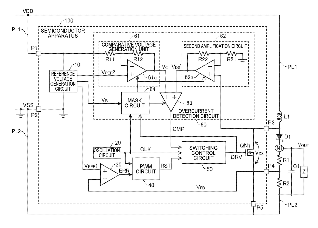
[0031]The following describes an embodiment of the invention in detail with reference to the drawings. Note that the same constituent elements are given the same reference signs to omit redundant explanations. FIG. 1 is a circuit diagram showing an exemplary configuration of a power supply apparatus according to an embodiment of the invention. In the following embodiment, a switching regulator (a DC-to-DC converter) that steps up a power supply voltage will be described as an example of the power supply apparatus.

Switching Regulator

[0032]As shown in FIG. 1, this switching regulator includes the following elements according to an embodiment of the invention: a semiconductor apparatus 100, an inductor L1, a diode D1, resistors R1 and R2, and a capacitor C1.

[0033]In the switching regulator, a first power supply line PL1 supplies a power supply potential VDD of a high-potential side, and a second power supply line PL2 supplies a power supply potential VSS of a low-potential side. The po...


PUM


Abstract

The present overcurrent detection circuit includes: a comparative voltage generation unit that generates a comparative voltage that changes in accordance with a power supply voltage; and a comparison unit that generates a comparison result signal by comparing a drain-source voltage of a switching transistor with the comparative voltage.

Description

[0001]This application claims the benefit of the Japanese Patent Application No. 2016-245140, filed on Dec. 19, 2016. The content of the aforementioned application is incorporated herein by reference in its entirety.BACKGROUND1. Technical Field[0002]The present invention relates to an overcurrent detection circuit used in, for example, a switching regulator that increases or decreases a power supply voltage. The invention further relates to, for example, a semiconductor apparatus having such an overcurrent detection circuit built therein, and a power supply apparatus that uses such a semiconductor apparatus.2. Related Art[0003]In a switching regulator that supplies current to an inductor by controlling ON and OFF of a switching transistor of an output circuit, current flowing through the switching transistor is detected in order to prevent the flow of overcurrent, for example. In general, a current sense resistor is connected in series to the switching transistor so as to detect cur...

Claims


Application Information

Patent Timeline
IPC IPC(8): H02H3/087H02M3/156
CPCH02H3/087H02M3/156G01R19/16571H01L29/78H02M1/32H02M3/158H02M1/0054H01L27/0266H02M1/0009Y02B70/10
Inventor KUWANO, TOSHIKAZU
Owner SEIKO EPSON CORP
Features
  • R&D
  • Intellectual Property
  • Life Sciences
  • Materials
  • Tech Scout
  • Unparalleled Data Quality
  • Higher Quality Content
  • 60% Fewer Hallucinations
Learn More