Microneedle arrays and methods for making and using

a micro-needle and array technology, applied in the field of micro-needle arrays, can solve the problems of ineffective oral administration of some benefit agents, pain and inconvenience, and conventional hypodermic needles

Active Publication Date: 2018-06-28
JOHNSON & JOHNSON CONSUMER COPANIES
View PDF4 Cites 17 Cited by
  • Summary
  • Abstract
  • Description
  • Claims
  • Application Information

AI Technical Summary

Benefits of technology

[0011]Surprisingly, we have found that an array of differing microneedles can be accurately achieved including a film having first and second, outwardly facing major surfaces. The first, outwardly facing major surface has a plurality of stratum corneum piercing microneedles extending therefrom, and the plurality of microneedles includes a plurality of first microneedles having a first benefit agent and a plurality of second microneedles having a second benefit agent.

Problems solved by technology

For example, oral administration of some benefit agents may be ineffective because the benefit agent is destroyed in the gastrointestinal tract or eliminated by the liver, both of which are avoided by transdermal drug delivery.
Parenteral injection with a conventional hypodermic needle also has drawbacks, as it is often painful and inconvenient.
However, there are obstacles to its use.
In particular, the physical barrier properties of the stratum corneum of human skin pose a significant challenge to transdermal drug delivery.
These barrier properties only allow relatively small molecules to be transported through the intact stratum corneum, and many useful drugs are too large to pass through the stratum corneum without some type of modification of the stratum corneum or other transport enhancement.
However, these methods may be inadequate to assist in the delivery of many medications through an intact skin layer and / or they may be inconvenient or undesirably complicated to use.
If solid microneedle arrays are kept in the skin, then the drug cannot readily flow into and through the holes in the skin because the holes remain plugged by the microneedles.
This method has been shown to significantly increase the skin's permeability; however, this method provides only limited ability to control the dosage and quantity of delivered drugs or vaccine.
Although this method provides somewhat better dosage control, it greatly limits the quantity of drug delivered.
Also, the deposition process is unreliable, and the thin layer of drug formulation on the microneedle could be easily chipped off of the microneedle during storage, transport, or administration (insertion) of the microneedles.
The application of a thicker and stronger layer of drug formulation can be undesirable because it reduced the sharpness of the microneedles and therefore made insertion more difficult and painful.
This shortcoming has limited the widespread application of this approach and precludes, for example, the simultaneous delivery of optimal quantities of combinations of antigens and / or adjuvant in vaccine applications.
However, reservoir-based microneedle arrays are expensive to make and require complex and expensive micromachining procedures.
In particular, it is difficult to make sharp tips on hollow microneedles with machining techniques.
Consequently, insertion of the microneedles into a patient's skin can be difficult and often painful.
In addition, the central bore of the microneedle is quite small and may be easily plugged by skin tissue during the insertion process, thereby blocking the drug delivery conduit.
However, lithographic and laser-based technologies are limited in the range of geometric features they can create, and the materials to which they can be applied.
Also, these highly complex fabrication technologies do not allow rapid or low cost fabrication of master molds, which can be particularly useful for systematic testing of the bio-effectiveness of various different microneedle and array geometries.
Finally, the microcasting process for producing dissolvable polymer-based microneedle arrays is limited to producing arrays of a single composition.
If there is a desire for personalized treatment requiring dissolvable arrays using microneedles with different compositions or benefit agents, the microcasting process cannot produce such arrays.
However, considerable practical limitations exist in the design, fabrication, and testing associated with microneedle arrays constructed using conventional processes.

Method used


Image

  • Microneedle arrays and methods for making and using
  • Microneedle arrays and methods for making and using
  • Microneedle arrays and methods for making and using

Examples


second embodiment

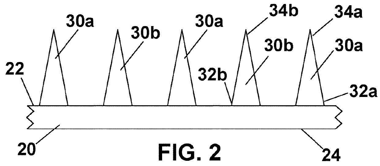
[0032]Microneedles 30 in microneedle array 10 of the invention may also be of a variety of lengths and geometries. FIG. 4 is a cross-sectional view of a section of a second embodiment microneedle array. In this embodiment, plurality of first stratum corneum piercing microneedles 30a comprise a first benefit agent and plurality of second stratum corneum piercing microneedles 30c comprise a second benefit agent. In addition, plurality of first microneedles 30a extend from first outwardly facing major surface 22 of film 20 to a height of h1, while plurality of second microneedles 30b extend from first surface 22 of film 20 to a height of h2. In this embodiment, there may be a desire for a deeper penetration into the skin of the user for first benefit agent contained in plurality of first microneedles 30a than from second benefit agent contained in plurality of second microneedles 30b.

[0033]Although the figure shows first stratum corneum piercing microneedles 30a are of uniform height ...

third embodiment

[0036]FIG. 5 is a cross-sectional view of a section of a third embodiment microneedle array showing a variety of stratum corneum piercing microneedle shapes. Microneedle 30a is conical in shape, with a taper from proximal end 32a to distal end 34a. Microneedle 30d has a cylindrical proximal end 32d, which tapers to a point at distal end 34d. Microneedle 30e has a proximal end 32e and a distal end 34e, and has an undulating shape. Microneedle 30f is cylindrical in shape, with no taper from proximal end 32f to distal end 34f. Finally, microneedle 30g is pyramidal in shape, with a taper from proximal end 32g to distal end 34g.

[0037]Although FIG. 5 shows all stratum corneum piercing microneedles 30 of substantially uniform height, it is to be understood that in other embodiments the microneedles may be of any number of different heights. In addition, microneedles 30a, 30d, 30e, 30f, and 30g comprise at least one benefit agent. Some comprise a first benefit agent, while others comprise ...

fourth embodiment

[0038]Microneedle arrays 10 of the present invention may also comprise stratum corneum piercing microneedles 30 comprised of multiple compositions. FIG. 6 is a cross-sectional view of a section of a fourth embodiment microneedle array 10 with such microneedles. The figure shows four different microneedles, with the microneedles being of variable heights, and comprising at least two distinct benefit agents. Microneedle 30h has a cylindrical proximal end 32h, which tapers to a point at distal end 34h. In addition, proximal end 32h of microneedle 30h is of a different composition than distal end 34h of microneedle 30h. Microneedle 30i is cylindrical, and has a core section 32i and a sheath section 34i. Here, core section 32i is of a different composition than sheath section 34i. Microneedle 30j has a cylindrical proximal end 32j and a cylindrical distal end 34j, and has a substantially linear form. Here, proximal end 32j of microneedle 30j is of a different composition than distal end ...


PUM


Abstract

An array of differing microneedles can be accurately achieved including a film having first and second, outwardly facing major surfaces. The first, outwardly facing major surface has a plurality of stratum corneum piercing microneedles extending therefrom, and the plurality of microneedles includes a plurality of first microneedles having a first benefit agent and a plurality of second microneedles having a second benefit agent.

Description

FIELD OF THE INVENTION[0001]The present invention relates to devices for the transdermal administration of benefit agents to patients through the skin. More particularly, this invention relates to microneedle arrays comprising a plurality of benefit agents, and methods for making and using these arrays.BACKGROUND OF THE INVENTION[0002]Transdermal drug delivery provides several advantages over other routes for administering a benefit agent formulation to a patient. For example, oral administration of some benefit agents may be ineffective because the benefit agent is destroyed in the gastrointestinal tract or eliminated by the liver, both of which are avoided by transdermal drug delivery. Parenteral injection with a conventional hypodermic needle also has drawbacks, as it is often painful and inconvenient.[0003]Transdermal drug delivery avoids these problems. However, there are obstacles to its use. In particular, the physical barrier properties of the stratum corneum of human skin p...

Claims


Application Information

Patent Timeline
Patent Type & Authority Applications(United States)
IPC IPC(8): A61M37/00
CPCA61M37/0015A61M2037/0053A61M2037/0023A61K9/0021A61M2205/02A61M37/00A61M2037/0046
Inventor ALARY, MARCHOPSON, PEYTONLIU, JAN-JOOLUNDE, ERIKPATEL, BHARAT
Owner JOHNSON & JOHNSON CONSUMER COPANIES
Why Eureka
Try Eureka