
Eureka
For R&D, Eureka makes reading and utilizing patents & technical documents easy.
Eureka AIR
Designed for self-driven R&D workflows. Generate viable solutions, solve complex R&D challenges, empower your innovation with AI.

Eureka Materials
Designed for material experts only. Revolutionize your material R&D, from search, analyze, to developing new materials.

TechResearch
Generate reliable direction feasibility study reports for your R&D in just a few steps.

TechSeek
Discover and master advanced knowledge NOW. Basics, ideas, possibilities, all at once.

TechMind
As an expert in R&D Theories, TechMind can generates customized viable solutions instantly.

TechRisk
Analyze your overall solution with one click, know your potential R&D risks in advance.

TechMonitor
Get weekly tech updates, stay abreast of the latest tech innovations and key insights.
Electrically-driven vehicle and control method for electrically-driven vehicle
- Summary
- Abstract
- Description
- Claims
- Application Information
AI Technical Summary
Benefits of technology
Problems solved by technology
Method used
Image

Examples
first embodiment
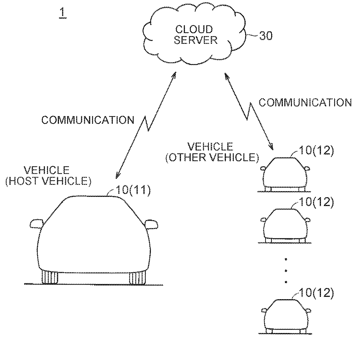
[0031]FIG. 1 is a schematic view that shows one example of an overall configuration of a vehicle control system 1 according to this first embodiment. The vehicle control system 1 includes plural vehicles 10 and a cloud server 30.
[0032]Each of the vehicles 10 is a so-called connected vehicle that is configured to be wirelessly communicable with the cloud server 30. Each of the vehicles 10 sends plural types of information that are related to vehicle travel such as a current position and a travel load (travel power) (hereinafter also simply referred to as “vehicle travel information”) to the cloud server 30 in specified cycles (for example, every few seconds).
[0033]The cloud server 30 stratifies and accumulates the information (the above-described vehicle travel information and the like), which is received from each of the vehicles 10, for each of the vehicles 10. In response to a request from each of the vehicles 10, the cloud server 30 is configured to be able to send data that is r...
modified example
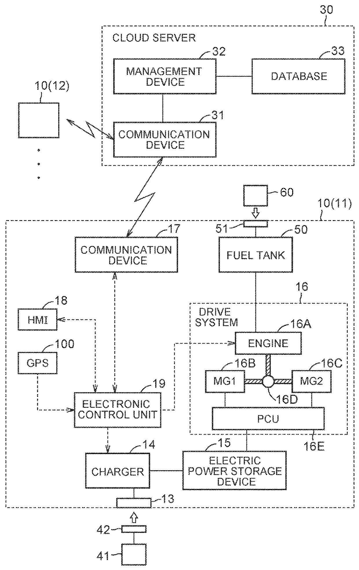
[0083]In the above-described first embodiment, the description has been made on the case where the host vehicle 11 is the plug-in hybrid vehicle that includes the engine 16A. However, in the above-described first embodiment, the host vehicle 11 is not necessarily limited to the plug-in hybrid vehicle and may be an electric vehicle that does not include an engine.
second embodiment
[0084]In the above-described first embodiment, the “threshold” (the reference level of the degree of the tightness in the electricity supply-demand balance) that is compared with the demanded electric power in step S14 of FIG. 4 is a fixed value.
[0085]Meanwhile, in this second embodiment, the above “threshold” is changed by using at least one of a degree of degradation of the fuel for the engine 16A, moisture content of oil (in a lubricant path), and a remaining amount of the fuel. Because the other configurations, functions, and processing are the same as those in the above-described first embodiment, the detailed description thereon will not be made herein.
[0086]Change of “Threshold” Using Degree of Degradation of Fuel for Engine 16A
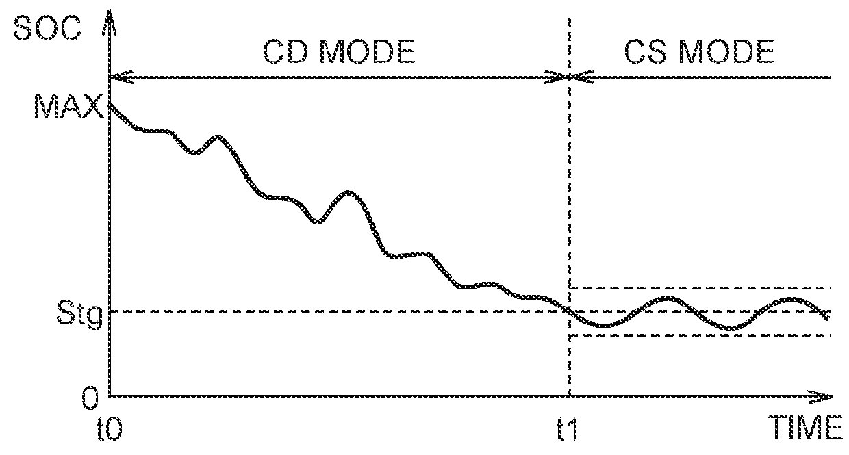
[0087]As it has been described so far, the CD mode is selected in the host vehicle 11 until the SOC of the electric power storage device 15 falls below the specified value Stg (see FIG. 3). In the CD mode, the EV travel is basically made, and the HV tr...
PUM
 Abstract
Description
Claims
Application Information
 - R&D Engineer
- R&D Manager
- IP Professional
- Industry Leading Data Capabilities
- Powerful AI technology
- Patent DNA Extraction
Browse by: Latest US Patents, China's latest patents, Technical Efficacy Thesaurus, Application Domain, Technology Topic, Popular Technical Reports.
© 2024 PatSnap. All rights reserved.Legal|Privacy policy|Modern Slavery Act Transparency Statement|Sitemap|About US| Contact US: help@patsnap.com