Material in-situ detection device and method under multi-load and multi-physical field coupled service conditions

a detection device and multi-physical field technology, applied in the direction of material strength using steady bending force, material strength using steady torsional force, etc., can solve the problems of only imposing a single load on equipment to evaluate the mechanical properties of the material, and unable to truly reflect the actual force state of the material

Active Publication Date: 2018-06-28
JILIN UNIV
View PDF5 Cites 23 Cited by
  • Summary
  • Abstract
  • Description
  • Claims
  • Application Information

AI Technical Summary

Benefits of technology

[0128]1. The structure is novel and the layout is compact. The applying of the composite load according to the present disclosure is mainly achieved by the precise six-degree-of-freedom composite load applying module and the precise torsion module. In addition to the individually loading the conventional four types of loads, i.e. “tension / compression-torsion-bending-indentation”, the loading of a composite load can also be achieved, such as “cantilever type pure bending, cantilever type tension / compression-torsion, cantilever type bending-torsion, cantilever type tension / compression-bending-torsion ” and other new loading method. The real simulation on the state of stress in material is performed under a condition close to the service condition of the material.
[0129]2. The device is generally designed with modular design in which a support frame module, a shock isolation platform, a precise six-degree-of-freedom composite load applying module, a precise torsion module, a clamp and electrothermal coupling module, a digital speckle strain measurement and infrared thermal imaging module, an in-situ observation module, a precise indentation module, a circumferential positioning module are included. Thereby the device can be standardized and is easy for maintenance.
[0130]3. The precise torsion module of the device structurally adopts a double thrust ball bearing structure to cancel the large impact force on the DC servo drive motor and the planetary gear reducer when the axial large load is tensed / compressed. The module also uses several micromotion universal balls, and in the large load compression—torsion test, the micromotion-universal balls between engaging surfaces can convert the sliding friction into rolling friction when the material is twisted, so as to reduce the impact of friction on the torsion.
[0131]4. The device provides a circumferential surrounding observation mode. The microscope can be circumferentially rotated around the axis of the test piece in the observation process by means of the integrated microscope, so that the deformation of microstructure in various directions in micro-deformation process of the observed material can be observed more comprehensively.
[0132]5. The clamp of the device is integrated with the function of loading cold / hot, electric and other multi-physical fields. By placing a silicon nitride ceramic heating sheet or a Peltier patch in the clamp, the test piece can be heated or cooled to effect the loading of the cold or hot field. The wire connected to the exterior is connected to the cable copper nose and the electric field is loaded in a manner of loading current.
[0133]6. The device adopts a novel non-contact optical strain measurement—digital speckle technology. By using this technique, the overall strain of the test piece under the coupling of the composite load of the multi-physics fields can be dynamically measured, showing the strain amplitude at any position and the position of the stress and strain concentration.
[0134]7. The temperature of the device is controlled by using the infrared thermal imaging technology, so that the overall temperature distribution can be seen directly through the display screen. At the same time, the collected temperature value is fed back to the host computer and compared with the set temperature, thereby achieving a closed-loop feedback control.

Problems solved by technology

It has proposed that among many factors that affect the level of material testing and detection, the lack of the test technology and equipment operating under conditions close to the service conditions is a bottleneck that restricts the development of new materials and the development of high-end equipment manufacturing industry.
However, these instruments and equipment can only impose a single load to evaluate the mechanical properties of the material, and cannot truly reflect the actual force state of the material.
Therefore, the single function of the test instrument seriously restricts the development of the micro-test technology, and it is necessary to develop a micro-performance in-situ test device for the composite load multi-physics field coupling material.

Method used


Image

  • Material in-situ detection device and method under multi-load and multi-physical field coupled service conditions
  • Material in-situ detection device and method under multi-load and multi-physical field coupled service conditions
  • Material in-situ detection device and method under multi-load and multi-physical field coupled service conditions

Examples


Embodiment Construction

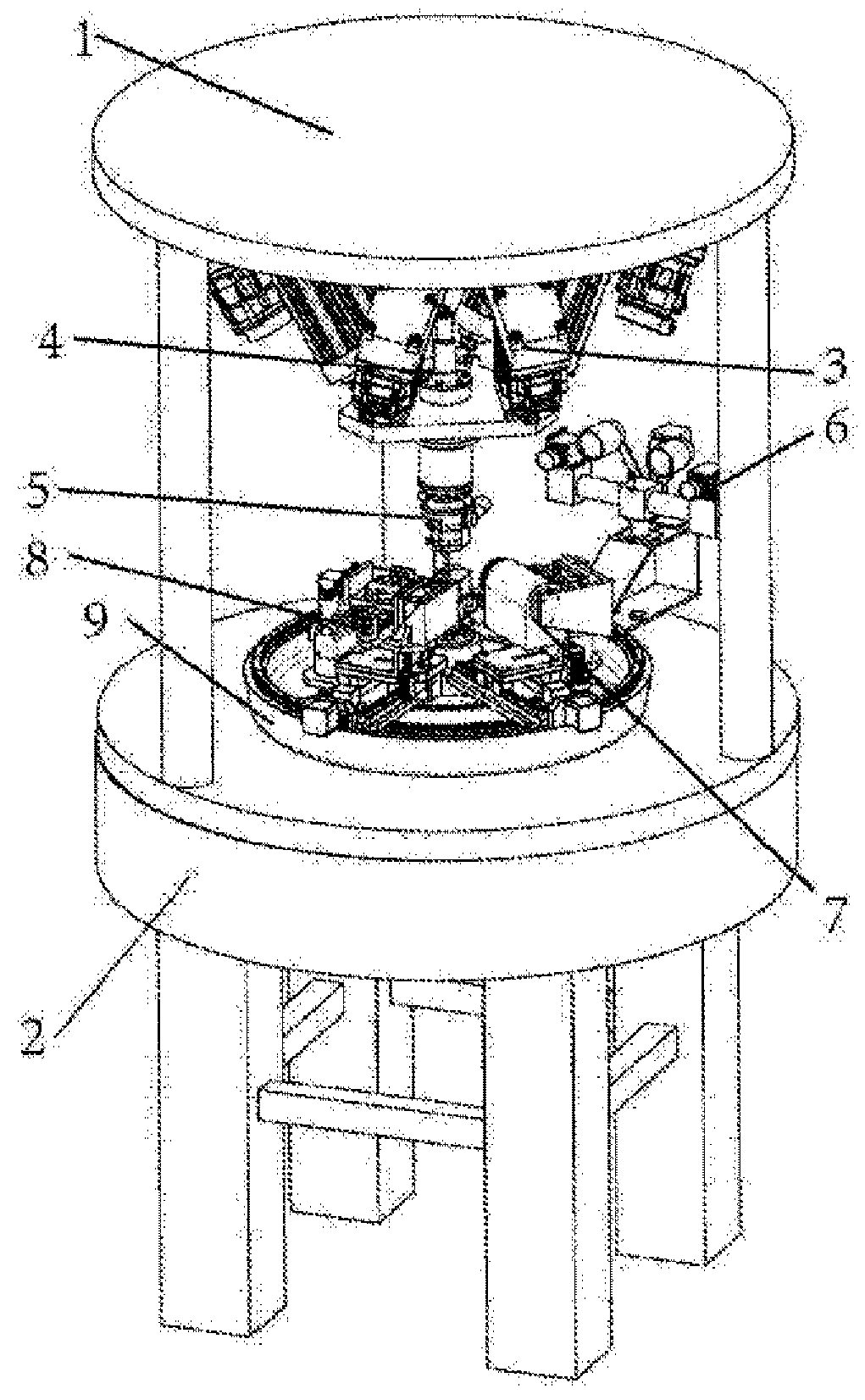
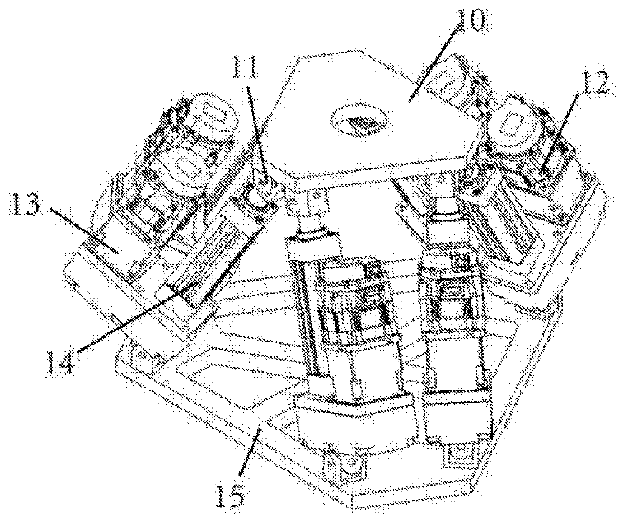
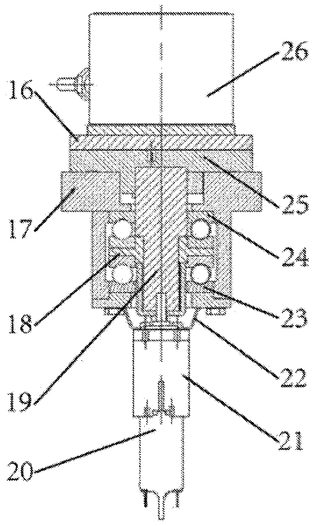
[0109]The details and the specific embodiments of the present disclosure will be further described with reference to the accompanying drawings.

[0110]An object of the present disclosure is to provide a material in-situ test device and method under multi-load and multi-physical field coupled service conditions so as to solve the problem that a compound load applying cannot be realized in the existing test technology. In addition to several types of the “tension / compression-torsion-bending-indentation” tests on the conventional testing machine, tests with novel loading methods of “cantilever type pure bending, cantilever type tension / compression-torsion, cantilever type bending-torsion, and cantilever type tension / compression-bending-torsion”, etc. can be carried out under the action of a composite load. At the same time combined with the loading of cold / hot-electric and other multi-physical fields, a multi-field and multi-load applying method is achieved. The strain of the test piece ...


PUM

PropertyMeasurementUnit
tension/compressionaaaaaaaaaa
degree of freedomaaaaaaaaaa
torqueaaaaaaaaaa

Abstract

Provided are a material in-situ test device and method under multi-load and multi-physical field coupled service conditions. The device is composed of a precise six-degree-of-freedom composite load applying module, a precise torsion module, a precise indentation module, a clamp module and a control module which work together to complete a composite-load and multi-physical field coupled experiment, and is integrated with a digital speckle strain measurement and infrared thermal imaging module and a microscope observation module, so as to carry out in-situ observation and quantitative characterization on material deformation behaviours and damage mechanism phenomena in a composite-load and multi-physical field loading process. For example, loading methods of “cantilever type pure bending, cantilever type tension / compression-torsion, and cantilever type bending-torsion”, etc. can realize the loading of composite load. Silicon nitride ceramic heating sheets, Peltier tiles and current loading are used for achieving simulation of multiple physical fields such as cold / hot-electricity fields.

Description

CROSS-REFERENCE TO RELATED APPLICATIONS[0001]This application is a Section 371 National Stage Application of International Application No. PCT / CN2015 / 090482, filed Sep. 24, 2015 and entitled with “MATERIAL IN-SITU TEST DEVICE AND METHOD UNDER MULTI-LOAD AND MULTI-PHYSICAL FIELD COUPLED SERVICE CONDITIONS”, which claims priority to Chinese Patent Application No. 201510422051.8, filed on Jul. 17, 2015 and entitled with “MATERIAL IN-SITU TEST DEVICE AND METHOD UNDER MULTI-LOAD AND MULTI-PHYSICAL FIELD COUPLED SERVICE CONDITIONS”, the contents of which are incorporated herein by reference in their entirety.FIELD OF THE DISCLOSURE[0002]The present disclosure relates to a field of precise scientific instruments and, more particularly, to a material in-situ test device and method under multi-load and multi-physical field coupled service conditions. In addition to several types of the “tension / compression-torsion-bending-indentation” tests on the conventional testing machine, tests with nov...

Claims


Application Information

Patent Timeline
Patent Type & Authority Applications(United States)
IPC IPC(8): G01N3/18G01N3/22G01N3/20
CPCG01N3/18G01N3/22G01N3/20G01N2203/0641G01N2203/0226G01N3/068G01N3/42G01N2203/0026G01N2203/0441G01N2203/0647
Inventor ZHAO, HONGWEIZHANG, SHIZHONGREN, LUQUANLI, NINGDAI, XIAOHANGWANG, SHUNBOHUO, ZHANWEILIU, YANGFANG, DAININGPEI, YONGMAO
Owner JILIN UNIV
Why Eureka
Try Eureka