Electric brake device

a technology of brake device and electric brake, which is applied in the direction of brake system, mechanical equipment, transportation and packaging, etc., can solve the problems of driver discomfort, driver discomfort, driver discomfort, etc., and achieve the effect of avoiding unnecessary adjustment of clearan

Active Publication Date: 2018-07-12
NTN CORP
View PDF2 Cites 3 Cited by
  • Summary
  • Abstract
  • Description
  • Claims
  • Application Information

AI Technical Summary

Benefits of technology

[0014]An objective of the present invention is to provide an electric brake device capable of adjusting a clearance without making a driver feel discomfort, in a vehicle equipped with an electric brake device.
[0019]In order to inhibit unnecessary change of the clearance and reduce occurrence frequency of noise, it is appropriate to perform control such that the clearance is kept eliminated when the vehicle is stopped with the brake operation member 27 being operated, and the clearance is kept as it is without being eliminated when the vehicle is stopped with the brake operation member 27 being not operated. In order to realize this control, the operation record flag as a flag for holding the record of the operation to the brake operation member 27 may be used. When determining the target clearance, the target clearance determination unit 17, by referring to the operation record flag, can prevent the clearance from being unexpectedly changed while the driver is not operating the brake operation member 27. Thus, the driver is prevented from feeling discomfort.
[0022]While the driver is not operating the brake operation member 27, the clearance adjustment section 30 adjusts the actual clearance so as to coincide with the target clearance with reference to the operation record flag. In this case, the clearance is not reduced zero from a value other than zero (e.g., stand-by position of the friction member 9) unless the brake operation member 27 has been operated just previously or immediately before the stop. Since useless adjustment of the clearance is avoided, unnecessary dragging torque can be reduced, thereby preventing decreasing electric mileage. Further, since the pressing command unit 18 and the target clearance determination unit 17 perform processing independently from each other, branching of conditional determination and determination of priority can be simplified.
[0024]According to this configuration, the vehicle stop detector 23 detects whether or not the vehicle is at a stop. The accelerator operation detector 21 detects whether or not the accelerator operation member 28 is being operated. The results are inputted to the target clearance determination unit 17. Further, the target clearance determination unit 17 receives the operation record flag, and determines the target clearance. Since the target clearance is determined based on not only the operation record flag but also the result as to whether or not the vehicle is at a stop and the result as to whether or not the accelerator operation member 28 is being operated, unnecessary change of the clearance can be inhibited, and occurrence frequency of noise can be reliably reduced.
[0030]During no operation being applied to the brake operation member 27, when the accelerator operation detector 21 detects that the accelerator operation member 28 is not being operated, the target clearance determination unit 17 may set the target clearance to a predetermined size other than zero when the operation record flag is “OFF” indicating a non-contact state where the friction member 9 is not in contact with the rotational member 8. In this case, the vehicle is stopped from inertial traveling without an operation to the brake operation member 27, or is traveling. The target clearance is then set to a clearance (other than zero) that allows the friction member 9 to be located at the stand-by position, whereby unnecessary adjustment of the clearance can be avoided.

Problems solved by technology

A driver is likely to feel discomfort when actual vehicle behavior in response to the driver's operation does not coincide with vehicle behavior expected by the driver, and when operation noise is generated at a time when the driver does not expect the noise generation.
Regarding the operation noise, even small noise is likely to make the driver feel discomfort if the noise is generated at an unexpected time.
This may make the driver feel discomfort.

Method used


Image

  • Electric brake device
  • Electric brake device
  • Electric brake device

Examples


Embodiment Construction

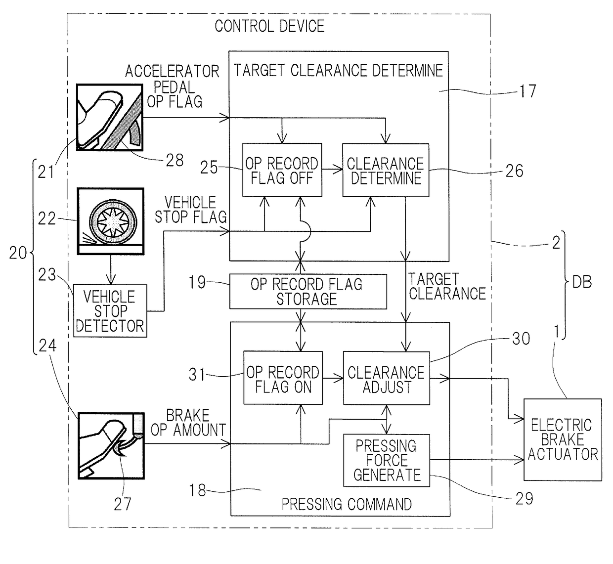
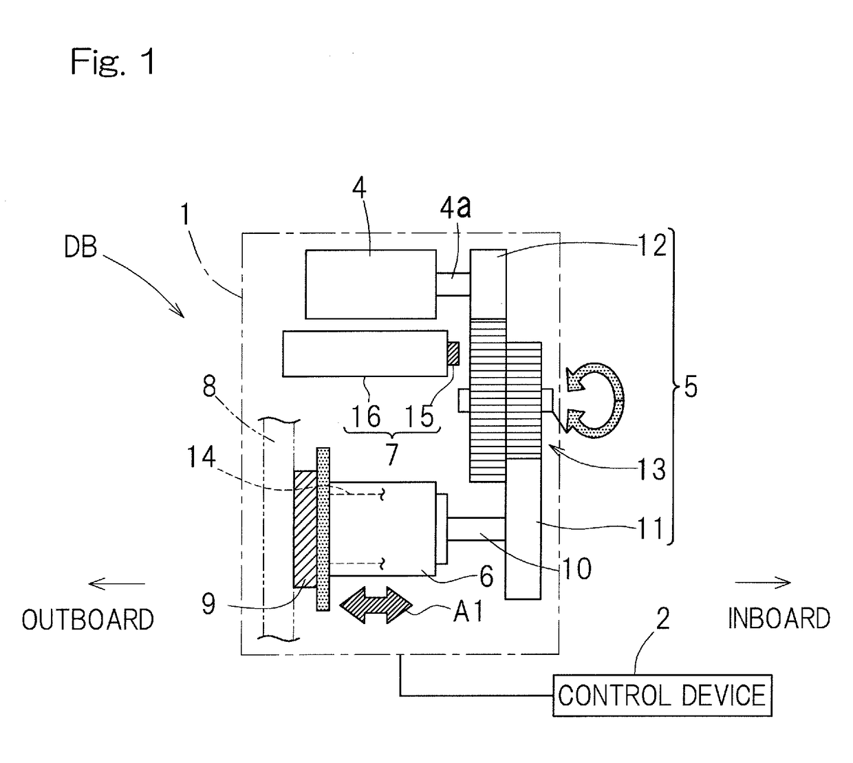
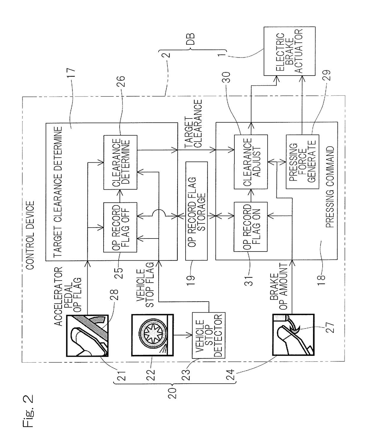
[0047]An electric brake device according to a first embodiment of the present invention will be described with reference to FIGS. 1 to 4. As shown in FIG. 1, an electric brake device DB includes an electric brake actuator 1, and a control device 2. First, the electric brake actuator 1 will be described.

[0048]The electric brake actuator 1 includes: an electric motor 4; a speed reduction mechanism 5 for reducing a speed of rotation of the electric motor 4; a linear motion mechanism 6 as a friction member operating mechanism; a parking brake mechanism 7 as a parking brake; a brake rotor 8 as a rotational member; and a friction member 9. The electric motor 4, the speed reduction mechanism 5, and the linear motion mechanism 6 are incorporated in, for example, a housing or the like (not shown). The brake rotor 8 may be a disk type or a drum type. The friction member 9 is a brake pad, a brake shoe, or the like. The linear motion mechanism 6 is a feed screw mechanism such as a ball screw me...


PUM


Abstract

Provided is an electric brake device capable of adjusting a clearance without making a driver feel discomfort, in a vehicle equipped with the electric brake device. A control device (2) of this electric brake device (DB) includes: a brake operation amount detector (24) to detect an operation amount to a brake operation member (27) of the vehicle; and an operation record flag storage unit (19) to store an operation record flag indicating a record of a latest operation performed by the driver to the brake operation member (27), on the basis of the operation amount detected by the brake operation amount detector (24). The control device (2) further includes a target clearance determination unit (17) to determine a target clearance with reference to the operation record flag stored in the operation record flag storage unit (19).

Description

CROSS REFERENCE TO THE RELATED APPLICATION[0001]This application is a continuation application, under 35 U.S.C. § 111(a), of international application No. PCT / JP2016 / 075880, filed Sep. 2, 2016, which claims Convention priority to Japanese patent application No. 2015-177242, filed Sep. 9, 2015, and Japanese patent application No. 2015-180302, filed Sep. 14, 2015, the entire disclosures of which are herein incorporated by reference as a part of this application.BACKGROUND OF THE INVENTIONField of the Invention[0002]The present invention relates to an electric brake device, and to a technique of adjusting a clearance without making a driver feel discomfort in a vehicle equipped with the electric brake device.Description of Related Art[0003]An electric brake is configured to be able to freely determine a clearance between a brake disc and a brake pad. As for a vehicle equipped with such an electric brake, various proposals have been made regarding: a control method for maintaining a tar...

Claims


Application Information

Patent Timeline
Patent Type & Authority Applications(United States)
IPC IPC(8): B60T8/172B60T13/74B60T8/171B60T7/04B60T8/32
CPCB60T8/172B60T13/741B60T2220/04B60T7/042B60T8/32B60T8/171B60T2201/12F16D55/226F16D65/183F16D2121/24F16D2125/40B60T13/74B60T8/00
Inventor NISHIKAWA, AKIYOSHIYAMASAKI, TATSUYA
Owner NTN CORP
Why Eureka
Try Eureka