Electronic control device

Active Publication Date: 2018-07-12
CONTINENTAL TEVES AG & CO OHG
View PDF12 Cites 22 Cited by
  • Summary
  • Abstract
  • Description
  • Claims
  • Application Information

AI Technical Summary

Benefits of technology

[0136]To this end, the excitation frequency can be varied continuously within a measurement range, for example between a lower frequency and an upper frequency. This allows the elimination of interference variables, which are typically active only in a narrow frequency range, so that during the variation the excitation frequency sweeps over a frequency of the interference var

Problems solved by technology

The resonant system has limitations for the conception of the inductive system, because only one oscillation per oscillator is possible.
Via the alteration of the oscillation frequency, cross-sensitivities can corrupt the measurement result, for example because the inductance L in addition to the sensitivity to

Method used


Image

  • Electronic control device
  • Electronic control device
  • Electronic control device

Examples


Example

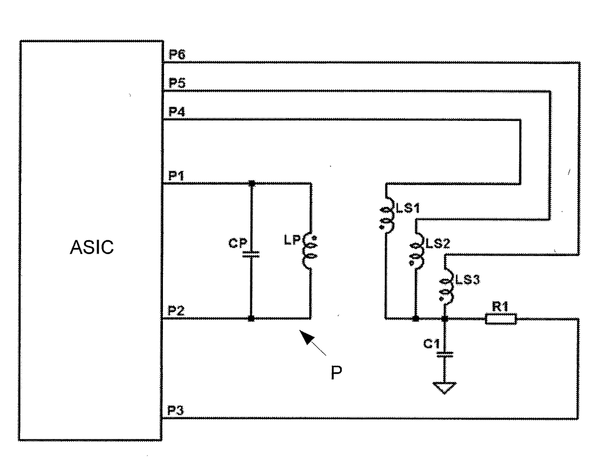
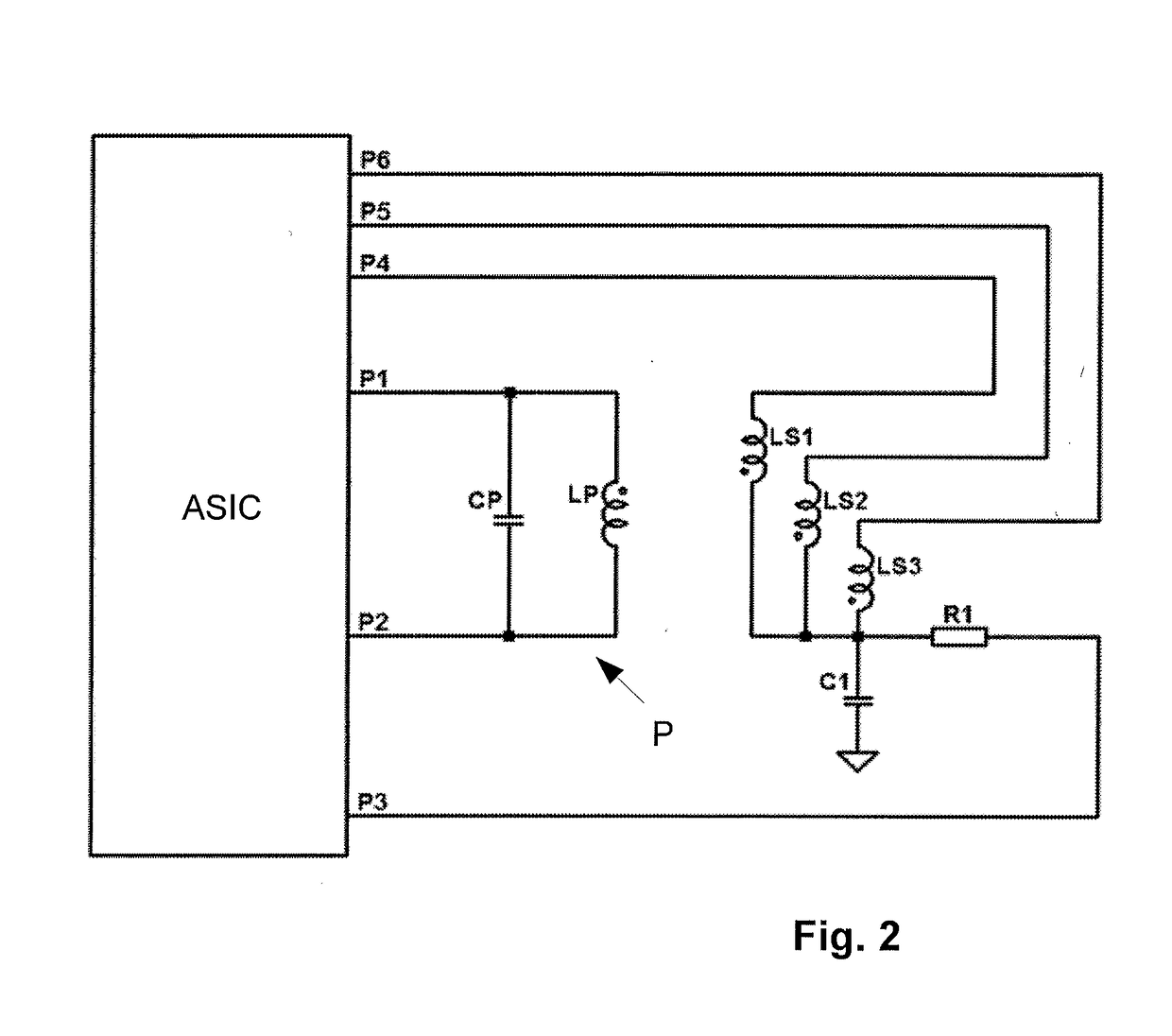
[0166]In the case of the apparatus according to the second exemplary embodiment, all the inductances are DC coupled. A parallel resonant circuit P is formed by a first inductance L1, a measurement inductance L2 and a capacitance CP. The measurement inductance L2 is sensitive to the measured variable and alters, while the first inductance L1 has a constant value. The connecting lines to the port pins P1, P2 contain resistors R2 and R3 that protect the port pins P1, P2 against excessively high currents. Between the first inductance L1 and the measurement inductance L2, a voltage is tapped off that oscillates at the stimulus frequency and whose amplitude and phase are dependent on the measured variable. For further aspects, reference is made to FIG. 2.

[0167]FIG. 4 shows possible internal circuitry at P1 and P2, particularly in the event of the use of a standard port pin of an ASIC or another electronic component in CMOS technology. An inverter is formed from MOS transistors M1 and M2, ...


PUM


Abstract

An electronic control unit for a device for measuring a measurement variable, wherein a first inductance is supplemented by a capacitance to form a parallel resonant circuit and is excited by a micro-controller. A measuring inductance coupled to the first inductance is measured by the electronic control unit. Therefore, a measured variable can be deduced and only very few components are required in addition to the electronic control unit.

Description

CROSS REFERENCE TO RELATED APPLICATIONS[0001]This application is the U.S. National Phase Application of PCT International Application No. PCT / EP2016 / 068158, filed Jul. 29, 2016, which claims priority to German Patent Application No. 10 2015 215 331.2, filed Aug. 11, 2015, the contents of such applications being incorporated by reference herein.FIELD OF THE INVENTION[0002]The invention relates to an electronic control unit for an apparatus for measuring a measured variable. In particular, such an apparatus may be an inductive sensor.BACKGROUND OF THE INVENTION[0003]Inductive sensors are typically based on a change in one or more characteristic values of a system of one or more inductive devices as a result of a measured variable. Inductive devices of this kind can refer to a coil, winding or inductance, for example.[0004]Possible characteristic values are, in particular:[0005]self inductance L, also called inductance for short,[0006]resistance loss R, which is made up of a nonreactiv...

Claims


Application Information

Patent Timeline
IPC IPC(8): G01D5/243G01R27/26G01B7/00G01B7/02
CPCG01D5/243G01R27/2605G01R27/2611G01B7/003G01B7/02
Inventor ACKER, HEINRICH
Owner CONTINENTAL TEVES AG & CO OHG
Why Eureka
Try Eureka