
Mm-wave sfcw radar and saf based imaging inspection system

a technology of sfcw radar and imaging inspection system, which is applied in the direction of geological detection using milimeter waves, radio wave reradiation/reflection, and using reradiation, etc., and can solve the problem of inability to measure signal phase, inability to retrieve depth information and permittivity profile, and inability to meet the low-contrast materials or material characterization.

Active Publication Date: 2018-07-12
OZ OPTICS
View PDF3 Cites 25 Cited by
  • Summary
  • Abstract
  • Description
  • Claims
  • Application Information

AI Technical Summary

Benefits of technology

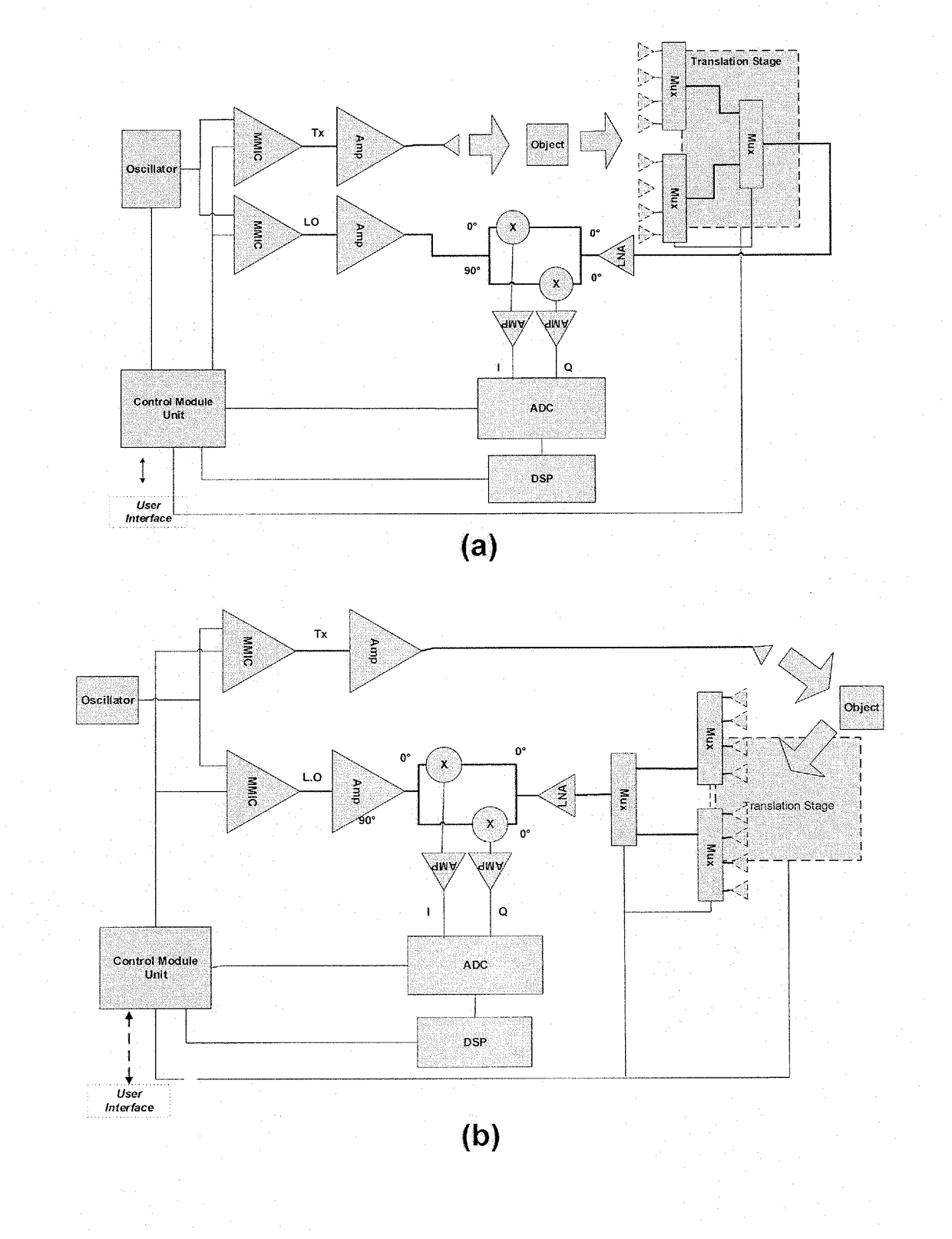
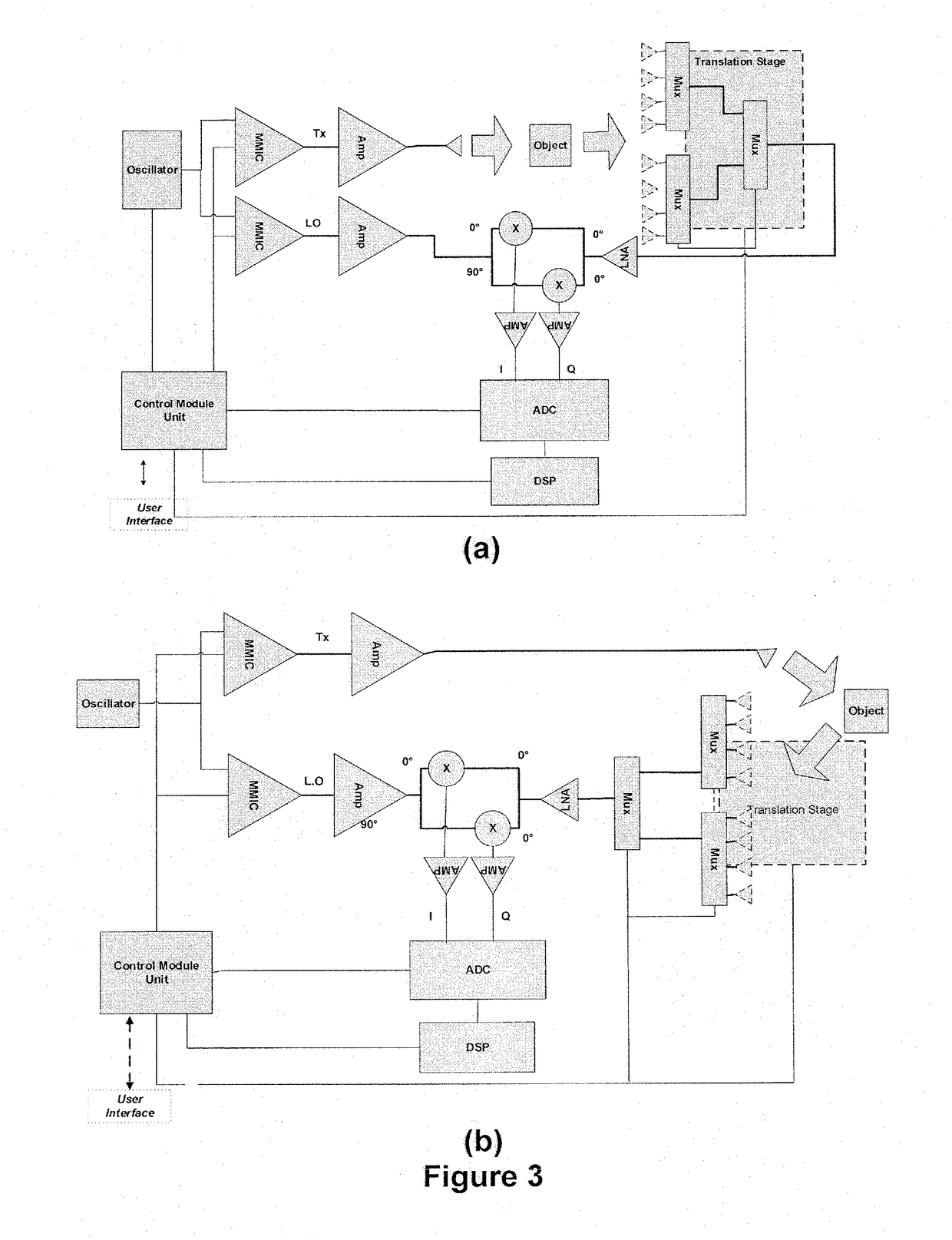
The present invention provides a flexible imaging inspection system that uses a special type of radar called Stepped Frequency Continuous Wave (SFCW). This system can work at different frequencies to perform different types of imaging and sensing. Its flexible design allows for efficient and effective inspection of objects or people.

Problems solved by technology

X-ray and ultraviolet radiation penetrates inside the package and can be used for imaging the high-contrast materials only in the package under test (PUT) but is not suitable for the low-contrast materials or material characterization.
The aforementioned imaging sensors and the imaging systems are able to measure the signal absorption, but unable to measure the signal phase.
Without recovering the phase information, the depth information and the permittivity profile cannot be retrieved.
Phase array antenna is a common option for recovering both the amplitude and phase information, but the phase array antenna implementation is very complex and expensive.

Method used


Image

  • Mm-wave sfcw radar and saf based imaging inspection system
  • Mm-wave sfcw radar and saf based imaging inspection system
  • Mm-wave sfcw radar and saf based imaging inspection system

Examples


Embodiment Construction

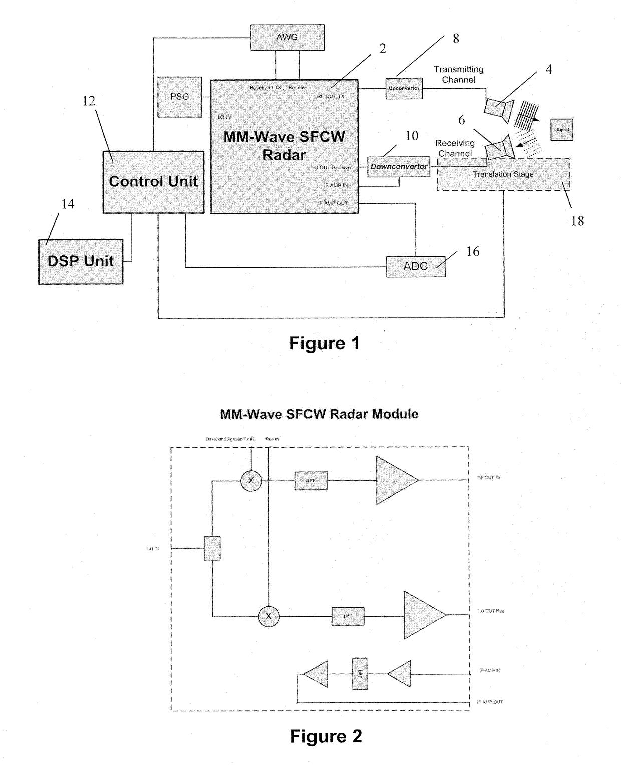
[0024]A low-cost flexible inspection imaging system is presented. The system block diagram is shown in FIG. 1. The flexible imaging inspection system consists of a MM-Wave SFCW Radar module 2, transmitting antenna 4, receiving antenna 6, frequency upconvertor 8, frequency downconvertor 10, control unit 12, digital signal processing (DSP) unit 14, analog to digital convertor 16, and a translation stage 18. The MM-Wave SFCW Radar module 2 generates the RF output signal, LO signal for down converting the receiving RF signal, and amplifies the IF signal for improving the Signal to Noise Ratio (SNR). The MM-Wave SFCW Radar module 2 block diagram is shown in FIG. 2. The transmitting channel includes the upconvertor 8 and transmitting antenna 4, and the receiving channel includes receiving antenna 6 (probe) and down convertor 10 as shown in FIG. 1. The control unit 12 synchronizes the interaction between all modules, reads the signal digitized by the Analog to Digital Converter (ADC) 16, a...


PUM


Abstract

The present invention presents a flexible, stepped frequency, radar based, imaging inspection system. The imaging inspection system can be used in airports, seaport sites, borders, postal processing centres, and sensitive sites. It comprises a millimetre-wave Stepped Frequency Continuous Wave (SFCW) radar module (2) connected to a transmitting channel and a receiving channel. The transmitting channel may comprise a frequency upconvertor (8) and the receiving channel may comprise a frequency downconvertor (10). A digital signal processing unit (14) reconstructs a conductivity profile and a permittivity profile of an object under test (OUT) from measurement data collected via a phase-array antenna or a translational stage (18) based on synthetic aperture focusing (SAF).

Description

CROSS REFERENCE TO RELATED APPLICATION[0001]This application claims priority to Jan. 8, 2018 Canadian Patent Application No. 2,953,984, filed on Jan. 9, 2017, the contents of which are incorporated herein by reference in its entirety.TECHNICAL FIELD[0002]The present invention pertains to a flexible, stepped frequency, radar based, imaging inspection, synthetic aperture focusing, and packaging inspection system.BACKGROUND OF THE INVENTION[0003]The exponential growth of e-commerce in conjunction with threats pertaining to the drug trade and terrorism are creating a significant need for inspection sites (postal processing centers, airports, seaports, border, and etc.) to upgrade and expand their capabilities. It is important to prevent hazardous and explosive materials, and illegal drugs transportation across international borders.[0004]The Millimeter-wave and Terahertz radiations are more suitable for the packaging inspection than other parts of spectrum, namely infrared, visible ligh...

Claims


Application Information

Patent Timeline
Patent Type & Authority Applications(United States)
IPC IPC(8): G01S13/88
CPCG01S13/887G01V8/005G01S2013/0263G01S13/38G01S13/90G01S2013/0245
Inventor SAFAVI-NAEINI, SAFIEDDINSHAHIR, SHAHED
Owner OZ OPTICS
Learn More