Optical film

a technology of optical film and film film, applied in the field of optical film, can solve the problems of large thickness of imaging film, difficult to cut imaging film in thermoprinting, and low resolution, and achieve the effects of good light collection ability, good adaptability and weather resistan

Active Publication Date: 2018-07-12
SHINE OPTOELECTRONICS KUNSHAN CO LTD
View PDF0 Cites 12 Cited by
  • Summary
  • Abstract
  • Description
  • Claims
  • Application Information

AI Technical Summary

Benefits of technology

[0030](4) an effect of a security element using a reflective random Moire amplified image is not affected by environmental light, and its surfaces are smooth and flat, and may bear such pollution as sweat stains, and oil, etc., may be applied with adhesive g

Problems solved by technology

As microlens imaging needs to be used and a substrate material needs to be ablated in this method, the resolution is relative low.
The overall thickness of the imaging film is generally large, which may r

Method used


Image

  • Optical film
  • Optical film
  • Optical film

Examples


embodiment 1

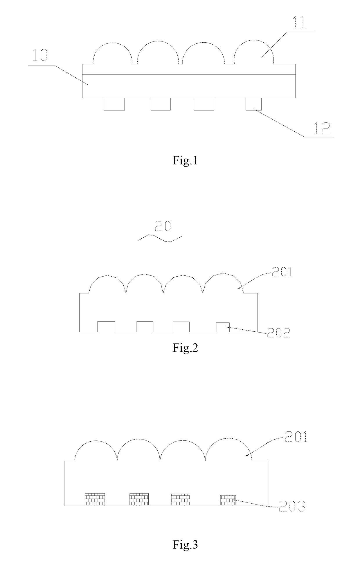
[0155]Referring to FIG. 17a, a schematic diagram of a structure of a 3D floating imaging optical film is shown. The film is of a structure having three layers: a transparent spacer layer 10, a 2D micro-focusing unit array layer (or a micro-focusing unit array) 11 and a micro graphic and text unit layer (micro graphic and text units) 12, micro-focusing units 13 and micro reflective units (or a micro reflective structure) 14 being on the 2D micro-focusing unit array layer 11.

[0156]A thickness of the transparent spacer layer 10 is between 10 microns and 5000 microns, and preferably less than 1000 microns. A material of the transparent spacer layer may be PC, PVC, PET, PMMA, a UV sensitive curing glue, a glass, or BOPP, etc., and preferably PET and a UV sensitive curing glue.

[0157]The micro-focusing units 13 and the micro reflective units 14 focus light incident from the second surface of the transparent spacer layer on the micro graphic and text unit layer 12. The micro-focusing units ...

embodiment 2

[0160]Referring to FIG. 15, a schematic diagram of a visual effect of a 3D stereoscopic imaging optical film is shown, such as the optical film described in Embodiment 1 of this disclosure, in which a micro graphic and text 44 hidden in the micro graphic and text layer is amplified to directly distinguished by eyes. Viewing from a side of the second surface of the transparent spacer layer, the viewer may see a unique amplified micro graphic and text 45 floating between the viewer and the second surface of the transparent spacer layer. No matter the imaging film is rotated around a horizontal axis 41 or around a vertical axis 42, no other amplified micro graphic and text will enter into the viewing region. Furthermore, as a micro-focusing unit 43 that functions is located on the second surface of the transparent spacer layer, it may be sealed by using a protective material. And when the first surface of the transparent spacer layer is covered by such transparent substances as water, ...

embodiment 3

[0161]In order to obtain the 3D optical imaging film based on the above technical solutions, this disclosure provides a method for preparing a 3D optical imaging film, including:

[0162]step 1: applying a UV curing glue or a thermally sensitive material on a side of a substrate layer and taking it as a micro reflective array layer;

[0163]step 2: curing a template press printed micro reflective array layer having a structure opposite to a to-be-pressed micro reflective structure by curing a UV curable glue by illumination or by curing a thermally sensitive material by cooling, so as to obtain the microlens array layer, the template press printed material consisting of Ni, NiCo, an alloy, an NiFe alloy, and NiSiC, etc., and a pressing printing manner being a plane-to-plane manner, or a roll-to-plane manner, or a roll-to-roll manner;

[0164]step 3: forming the micro reflective structure in the micro reflective array layer, such as a single-layer dielectric layer, or a multi-layer dielectric...


PUM

PropertyMeasurementUnit
Fractionaaaaaaaaaa
Fractionaaaaaaaaaa
Transparencyaaaaaaaaaa

Abstract

This application discloses an optical film, comprising: a polymer having a first surface and a second surface, the first surface and the second surface opposing to each other; a microlens structure being formed on the first surface, an accommodation structure being formed on the second surface, the accommodation structure accommodating a number of pattern structures imaging through the microlens structure; the microlens structure and the accommodation structure being integral; and the micro-focusing units and the pattern structures being adapted to each other, so that the optical film forms at least one image floating in the optical film when the optical film is viewed from a side of the pattern structures or a side of the micro-focusing units. A substrate layer is omitted from the optical film, hence, the optical film is reduced in thickness, and mechanical performance is not good, which makes the optical film easy to be cut in thermoprinting.

Description

CROSS REFERENCE TO RELATED APPLICATIONS[0001]This disclosure claims the benefits of Chinese patent applications No. 2015204898220, No. 2015103978701, No. 2015103974448, No. 2015204885165 and No. 2015204878689, filed on Jul. 8, 2015, and No. 2015106991727 and No. 2015208273793, filed on Oct. 23, 2015, and No. 2015103976689, filed on Jul. 8, 2015, which are incorporated herein by reference.FIELD[0002]This disclosure relates to the field of optical films, and in particular to an optical film.[0003]Brief Description of Related Developments More and more attention has been paid to various 3D imaging techniques in the fields of information, display, medicine, and military affairs, etc. It has wide potentials and foregrounds to achieve 3D imaging by using the microlens technique. It is developed from the integrated photography proposed by G. Lippman in 1908, in which a group of 2D unit images having different perspective relationships in a 3D scenario are collected and recorded by a lens a...

Claims


Application Information

Patent Timeline
IPC IPC(8): G02B1/04G02B1/18G02B27/22G02B3/00
CPCG02B1/04G02B1/18G02B27/22G02B3/00B42D25/324B42D25/342G02B1/041G02B3/0043G02B30/00G02B30/27
Inventor ZHANG, JIAN
Owner SHINE OPTOELECTRONICS KUNSHAN CO LTD
Why Eureka
Try Eureka