Unlock instant, AI-driven research and patent intelligence for your innovation.

Microscopic three-dimensional measurement system and method based on moving diaphragm

a three-dimensional measurement and moving diaphragm technology, applied in the field of microscopic three-dimensional measurement technology, can solve the problems of severe defocus phenomenon, small field of view of optical microscope, shallow depth of field, etc., and achieve the effect of reducing measurement errors

Active Publication Date: 2018-07-12
NINGBO UNIV
View PDF2 Cites 1 Cited by
  • Summary
  • Abstract
  • Description
  • Claims
  • Application Information

AI Technical Summary

Benefits of technology

The present invention provides a microscopic three-dimensional measurement system and method based on a moving diaphragm. By using the diaphragm to extend the depth of field and the depth measurement range, the system can achieve the three-dimensional measurement of large-size objects. The depth of field is enlarged and the imaging model has certain non-linear characteristics, which reduces the measurement error. The technical effect of the invention is to improve the accuracy and efficiency of microscopic three-dimensional measurement.

Problems solved by technology

However, the optical microscope has disadvantages of small field of view, severe defocused phenomenon and shallow depth of field.
Therefore, if the size of the three-dimensional object to be observed exceeds the shallow depth of field of the optical microscope, the clear left images and the clear right images of the three-dimensional object to be observed are difficult to be obtained, which eventually leads that the three-dimensional measurement cannot be achieved.

Method used


Image

  • Microscopic three-dimensional measurement system and method based on moving diaphragm
  • Microscopic three-dimensional measurement system and method based on moving diaphragm
  • Microscopic three-dimensional measurement system and method based on moving diaphragm

Examples


Embodiment Construction

[0052]The present invention is further described in detailed with accompanying drawings and embodiments as follows.

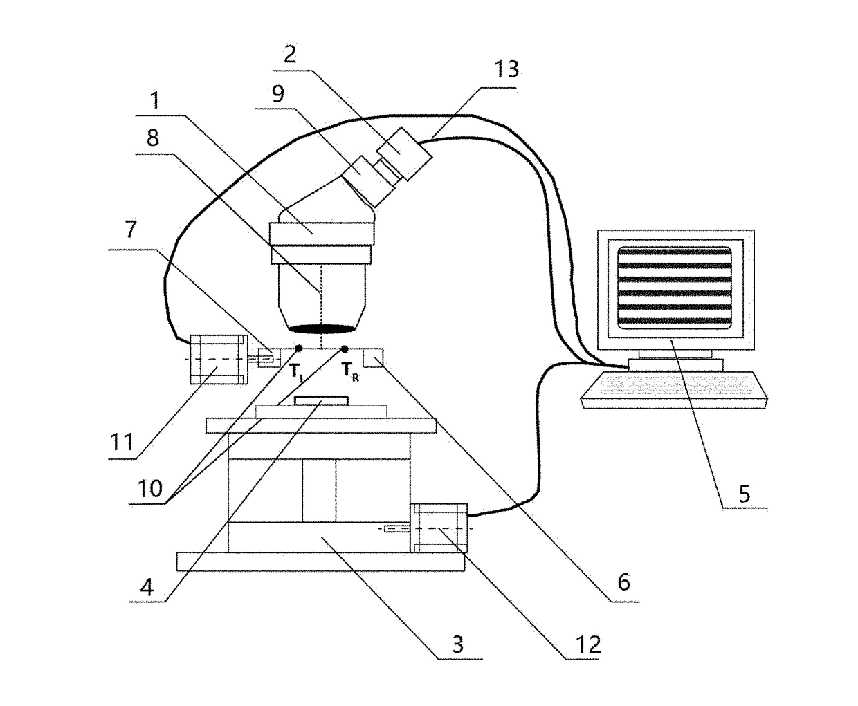
[0053]The present invention provides a microscopic three-dimensional measurement system based on a moving diaphragm, as shown in FIG. 1, which comprises an optical microscope 1, a camera 2 which is installed on the optical microscope 1 and is aligned with an eyepiece 9 of the optical microscope 1, a lifting platform 3 for horizontally placing a dot calibration board 4, and a computer 5, wherein the optical microscope 1 is disposed above the dot calibration board 4 for allowing the eyepiece of the optical microscope 1 to just face towards the dot calibration board 4, an output end 13 of the camera 2 is connected with the computer 5, a drive motor 12 of the lifting platform 3 is connected with the computer 5; a diaphragm 6, which is able to horizontally move, is disposed between the eyepiece of the optical microscope 1 and the dot calibration board 4;

[0054]an optical axis...


PUM


Abstract

The present invention discloses a microscopic three-dimensional measurement system and method based on a moving diaphragm. The present invention adds the diaphragm into the existing optical microscopic imaging system to limit light irradiation angle during imaging for reducing the diameter of blur circle, which extends the depth of field and the depth measurement range, so as to achieve the three-dimensional measurement of large-size objects to be measured. Through changing the position of the added diaphragm, two images with different light incident directions are obtained, which is similar to binocular stereo vision, and then the disparity map is used to predict the depth, so as to carry out the 3D scene reconstruction. Since the depth of field of the imaging system is enlarged and the imaging model has certain non-linear characteristics, the present invention uses quadratic function to express the non-linearity, which reduces the measurement error.

Description

CROSS REFERENCE OF RELATED APPLICATION[0001]The present invention claims priority under 35 U.S.C. 119(a-d) to CN 201711144614.7, filed Nov. 17, 2017.BACKGROUND OF THE PRESENT INVENTIONField of Invention[0002]The present invention relates to a microscopic three-dimensional measurement technology, and more particularly to a microscopic three-dimensional measurement system and method based on a moving diaphragm.Description of Related Arts[0003]The optical microscope is a commonly used three-dimensional micro-measuring instrument, which is used to measure three-dimensional coordinates of space points and obtain experimental data in biomedicine, quality inspection and industrial micromanipulation, for facilitating quantitative analysis, so as to improve the product quality, improve the manufacturing process and ensure the accuracy of scientific research.[0004]Currently, digital stereomicroscopes are often used to achieve microscopic three-dimensional measurements. The computer acquires l...

Claims


Application Information

Patent Timeline
IPC IPC(8): H04N5/232G06T7/593H04N5/235H04N5/238G02B21/36G02B21/26
CPCH04N5/23212G06T7/593H04N5/2354H04N5/238H04N2013/0081H04N13/275G02B21/362G02B21/26G06T2200/08G06T2207/10056H04N13/271H04N5/23216G01B11/24G01B11/25H04N23/67G02B21/0016H04N13/246H04N13/239H04N23/62H04N23/74H04N23/75
Inventor JIANG, GANGYIYU, MEIFAN, SHENGLIWANG, YIGANG
Owner NINGBO UNIV