Compositions for use in fused filament 3D fabrication and method for manufacturing same

a technology of fused filament and composition, applied in the field of 3d printing, can solve the problems of poor chemical resistance of amorphous polymers, lower heat resistance, lower dimensional stability, and higher creep, and achieve the effect of improving chemical resistance and superior mechanical strength

Inactive Publication Date: 2018-07-19
AREVO INC
View PDF31 Cites 5 Cited by
  • Summary
  • Abstract
  • Description
  • Claims
  • Application Information

AI Technical Summary

Benefits of technology

[0008]In accordance with an illustrative embodiment, a method for forming a blended material for use as a deposition material in a fused filament fabrication printer is provided. A semi-crystalline material and an amorphous material are physically mixed at an appropriate ratio. The mixed material is then heated to a temperature that is above the melting point of the semi-crystalline material and above the glass transition temperature of the amorphous material to form a blended material. The blended material is then extruded through an extruder die for use in the FFF printer. Advantageously, the blended material allows printing of a 3D object with semi-crystalline material to provide increased chemical resistance and superior mechanical strength.

Problems solved by technology

Unfortunately, amorphous polymers tend to have poor chemical resistance, lower heat resistance, lower dimensional stability and higher creep.
That is why most objects formed via fused filament fabrication cannot be used in more demanding applications such as in aerospace, oil a gas and healthcare industries.
However, attempts to “print” the semi-crystalline material with a fused filament fabrication process have been unsuccessful.
This is because the highly viscous nature of the material causes clogging in the extrusion printhead and even when printed, the semi-crystalline material does not solidify fast enough to hold its shape.

Method used


Image

  • Compositions for use in fused filament 3D fabrication and method for manufacturing same
  • Compositions for use in fused filament 3D fabrication and method for manufacturing same

Examples


Embodiment Construction

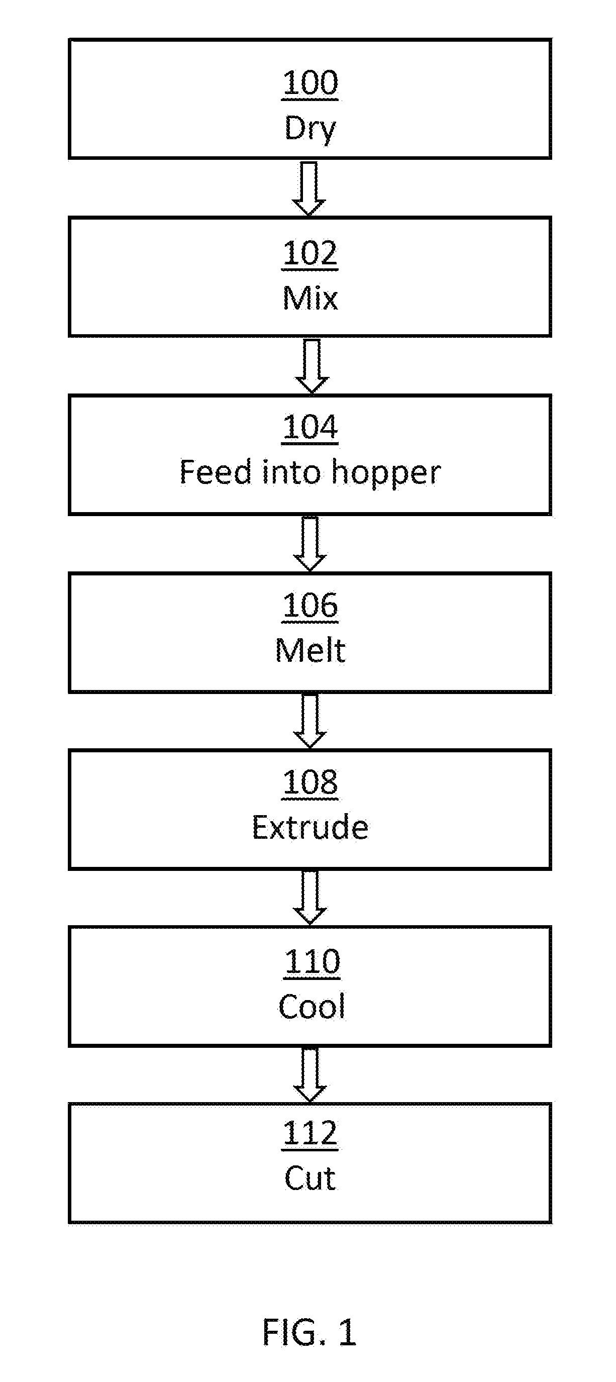
[0013]Printing with the blended material results in 3D objects having more desirable mechanical properties and chemical resistance than would be possible using an amorphous material alone. This results from the presence of the semi-crystalline material in the blend, which is characterized by significantly better chemical resistance and mechanical properties such as tensile strength.

[0014]In one embodiment, the blend is a mixture of polyphenylsulfone (PPSU), representing the amorphous polymer, and polyether ether ketone (PEEK) as the semi-crystalline material.

[0015]In some other embodiments, other amorphous materials, such as other polyarylsulfones (e.g., polyethersulfone (PESU), polysulfone (PSU), etc.) can be used in conjunction with PEEK to form a blended material in accordance with the present teachings and suitable for use in a fused filament fabrication process. Still further, other amorphous materials can be used in conjunction with PEEK or other semi-crystalline materials to ...


PUM

PropertyMeasurementUnit
lengthaaaaaaaaaa
temperatureaaaaaaaaaa

Abstract

A method for forming a blended material for use as a deposition material in a fused filament fabrication (FFF) printer is provided. A semi-crystalline material and an amorphous material are physically mixed at an appropriate ratio. The mixed material is then heated to a temperature that is above the melting point of the semi-crystalline material and above the glass transition temperature of the amorphous material to form a blended material. The blended material is then extruded through an extruder die for use in the FFF printer.

Description

CROSS-REFERENCE TO RELATED APPLICATIONS[0001]This application claims the benefit of U.S. Provisional Application Ser. No. 61 / 951,720, filed Mar. 12, 2014, entitled “COMPOSITIONS AND METHODS FOR USE IN FUSED FILAMENT FABRICATION PROCESSES”, which is incorporated herein by reference, and is a continuation of U.S. application Ser. No. 14 / 297,185, filed on Jun. 5, 2014, entitled COMPOSITIONS FOR USE IN FUSED FILAMENT 3D FABRICATION AND METHOD FOR MANUFACTURING SAME.FIELD OF THE INVENTION[0002]This invention pertains to 3D printing and in particular, materials for use in fused filament fabrication.BACKGROUND OF THE INVENTION[0003]Fused filament fabrication (“FFF”), also known as fused deposition modeling, is an additive manufacturing technology typically used for modeling, prototyping, and in some cases even production applications. This process fabricates a three-dimensional (“3D”) object from a mathematical model of the object using materials such as thermoplastics and metals that are ...

Claims


Application Information

Patent Timeline
Patent Type & Authority Applications(United States)
IPC IPC(8): C08J3/00B29C64/141C08J3/20B29C48/02B29C48/92
CPCC08J2469/00B29C64/141C08J2377/00C08J2471/12C08J2479/08C08J2481/06C08J3/203C08J3/005C08J2369/00B29L2031/731C08L67/02C08L69/00C08L71/123C08L77/00C08L79/08C08L81/06C08L71/00B29C47/0004B33Y70/00B33Y10/00C08J2367/02C08G2650/40B29C64/118B29C48/92B29C48/02B29C48/022B33Y70/10
Inventor BHEDA, HEMANTPATEL, KUNAL
Owner AREVO INC
Why Eureka
Try Eureka