Method for setting up a protective sealing layer in a landfill basin for industrial and mining slurries and geotextile protective tube mat for carrying out the method

a technology of geotextile protective tube mat and landfill basin, which is applied in landfill technology, construction, foundation engineering, etc., can solve the problems of significant environmental hazards, mechanical damage, and the bottom sealing layer is endangered by the effects, so as to prevent the rise of the geomembranes and/or uneven swelling of the bentonite web, reduce the height of the fully filled protective tube mat, and improve the effect of environmental protection

Active Publication Date: 2018-07-19
HUESKER SYNTHETIC GMBH & CO KG
View PDF0 Cites 0 Cited by
  • Summary
  • Abstract
  • Description
  • Claims
  • Application Information

AI Technical Summary

Benefits of technology

[0022]In one preferred application, the protective tube mat is installed on a bentonite-containing bottom sealing layer. By filling the tubes, on the one hand, water escapes and leads to the swelling of the bentonite. In addition, this also provides a ballast, which prevents rising of the geomembranes and/or uneven swelling of bentonite webs.
[0023]A geotextile suitable for carrying out the method is presented in claim 9 and comprises at least one lower and one upper layer, which are connected to each other via at least two parallel connecting lines, so that at least one flexible tube is formed between the connecting lines. Preferably, a subdivision into several flexible tubes takes place. Since the flexible tubes, which are initially lying flat, rise up rib-shaped during filling, a subdivision into a plurality of individual flexible tubes serves, in particular, to reduce the height of the fully filled protective tube mat.
[0024]Particularly advantageous is the use of a polypropylene fabric for the produc...

Problems solved by technology

However, the bottom sealing layer, usually consisting of a plastic sealing strip with additional layers is endangered by the effects of heat and UV radiation as well as due to mechanical damage.
The mechanical damage can result from driving and walking on the sealing level.
The bottom sealing layer is often damaged by drivin...

Method used


Image

  • Method for setting up a protective sealing layer in a landfill basin for industrial and mining slurries and geotextile protective tube mat for carrying out the method
  • Method for setting up a protective sealing layer in a landfill basin for industrial and mining slurries and geotextile protective tube mat for carrying out the method
  • Method for setting up a protective sealing layer in a landfill basin for industrial and mining slurries and geotextile protective tube mat for carrying out the method

Examples


Embodiment Construction

[0032]The preferred embodiments of the present invention will now be described with reference to FIGS. 1-5 of the drawings. Identical elements in the various figures are designated with the same reference numerals.

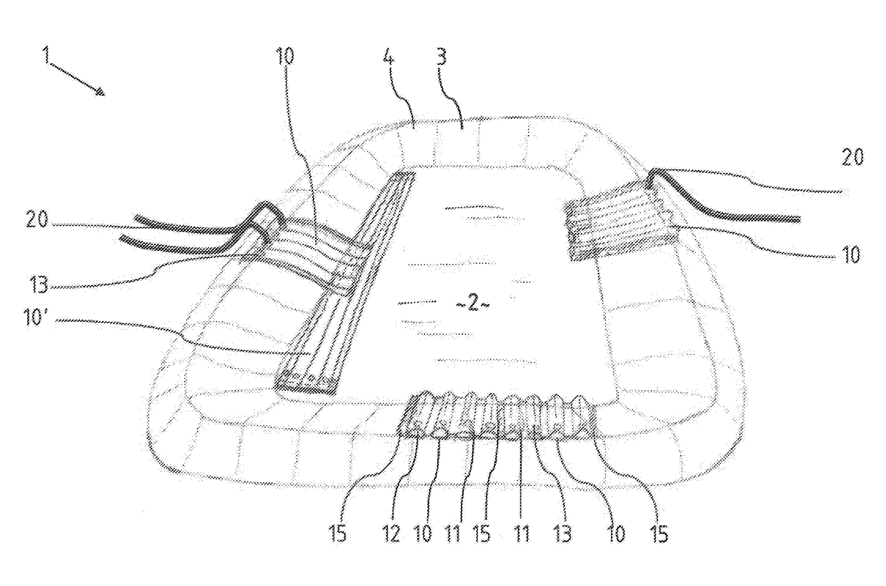
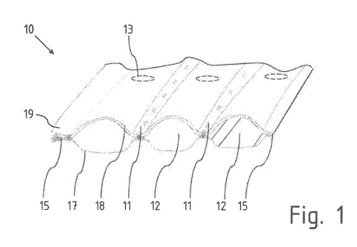
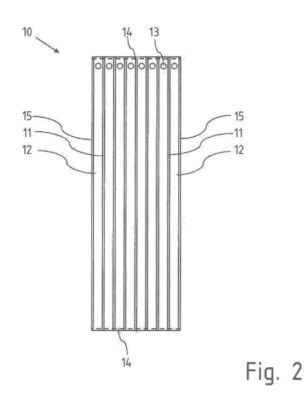
[0033]FIG. 1 shows a perspective sectional view of a protective tube mat 10 required for carrying out the method according to the invention. It consists of a lower layer 17 and an upper layer 18, which are each formed as a geotextile, wherein the layers 17, 18 are connected to each other, in particular woven together, along parallel connecting lines 15. An additional connecting line 15 exists at the respective outer edges. Additional fasteners, such as zippers, may be provided at the edges to connect adjacent protective tube mats without overlapping. Filling openings 13 serve to fill the flexible tubes 12 between the adjacent connecting lines 11 and between the interconnected layers 17, 18.

[0034]An additional UV protective layer 19 is applied to the upper layer 18. It is c...


PUM

PropertyMeasurementUnit
Flexibilityaaaaaaaaaa
Heightaaaaaaaaaa

Abstract

A method and geotextile protective tube mat for selling up a protective sealing layer in a landfill basin for industrial and mining slurries, wherein the landfill basin comprises at least a bottom area and an embankment ring, which are covered at least up to the height of a maximum filling level with a single-ply or multi-ply base sealing layer. The method includes the steps of: providing and using bottom protective tube mats (10), consisting of a water-permeable, multi-ply geotextile fabric, in which at least a lower ply (17) and an upper ply (18) are connected directly to one another along a number of parallel connecting lines (11; 15), wherein flexible tubes (12) are formed between neighboring connecting lines (11; 15) that are separate from one another and each have at least one filling opening (13); laying out the bottom protective tube mats (10) on the bottom area of the landfill basin; laying out embankment protective tube mats (10) on the embankment ring, wherein the flexible tubes (12) are aligned in the direction of the slope of the embankment or at an acute angle thereto; and filling each flexible tube (12) individually with an aqueous suspension and sealing the filling openings (13).

Description

BACKGROUND OF THE INVENTION[0001]The invention relates to a method for setting up a protective sealing layer in a landfill basin for industrial and mining slurries and a geotextile protective tube mat for carrying out the method.[0002]Slurry-like waste occurs in industrial processes, in particular in the mining industry. In the mining industry, these are, in particular, residues from the treatment of ores, which are present in the form of slurries and are referred to as tailing. These slurries are collected in so-called slurry ponds and stored permanently, whereby an absolute tightness of a sealing layer covering the bottom is required and this over a very long period, since it is usually a repository for the waste, thus remaining permanently in the slurry ponds. The production of a completely tight and against the substances contained in the slurries chemically resistant sealing level is basically possible according to the prior art. However, the bottom sealing layer, usually consi...

Claims


Application Information

Patent Timeline
IPC IPC(8): E02D31/00B32B1/08B32B5/26
CPCE02D31/004B32B1/08B32B5/26B32B2262/0253B32B2307/71Y02W30/30
Inventor WILKE, MARKUSBREYTENBACH, MORNE
Owner HUESKER SYNTHETIC GMBH & CO KG
Why Eureka
Try Eureka