Opposed Piston Engine

a piston engine and piston technology, applied in the direction of machines/engines, fuel air intakes, combustion air/fuel air treatment, etc., can solve the problems of increasing the burn length by a significant amount compared to known designs, and reducing the surface area of the chamber. , to achieve the effect of increasing the burn length and reducing the surface area of the chamber

Active Publication Date: 2018-07-19
HOLLAND RONALD A
View PDF18 Cites 3 Cited by
  • Summary
  • Abstract
  • Description
  • Claims
  • Application Information

AI Technical Summary

Benefits of technology

[0008]The present invention addresses the above and other needs by providing an opposed piston engine including approximately spherical combustion chamber formed by the two opposed pistons in a single cylinder and an intake manifold including gas hooks. The combustion chamber has a small cone shaped extension on each side leading to each of two opposed injectors located in the cylinder wall where the two pistons meet at the top of their stroke. The combustion chamber configuration reduces the surface area of the chamber and increases the burn length by a significant amount compared to known designs. The gas hooks in the intake manifold restrict the flow of exhaust gases into the intake manifold long enough for the pressure in the cylinder to blow down and the exhaust gasses to attain high velocity passing out through the exhaust manifold, allowing the intake ports to be uncovered before the exhaust ports.

Problems solved by technology

The combustion chamber configuration reduces the surface area of the chamber and increases the burn length by a significant amount compared to known designs.
This combustion chamber configuration reduces the surface area of the chamber and increases the burn length by a significant amount over all known prior art.

Method used


Image

  • Opposed Piston Engine
  • Opposed Piston Engine
  • Opposed Piston Engine

Examples


Embodiment Construction

[0034]The following description is of the best mode presently contemplated for carrying out the invention. This description is not to be taken in a limiting sense, but is made merely for the purpose of describing one or more preferred embodiments of the invention. The scope of the invention should be determined with reference to the claims.

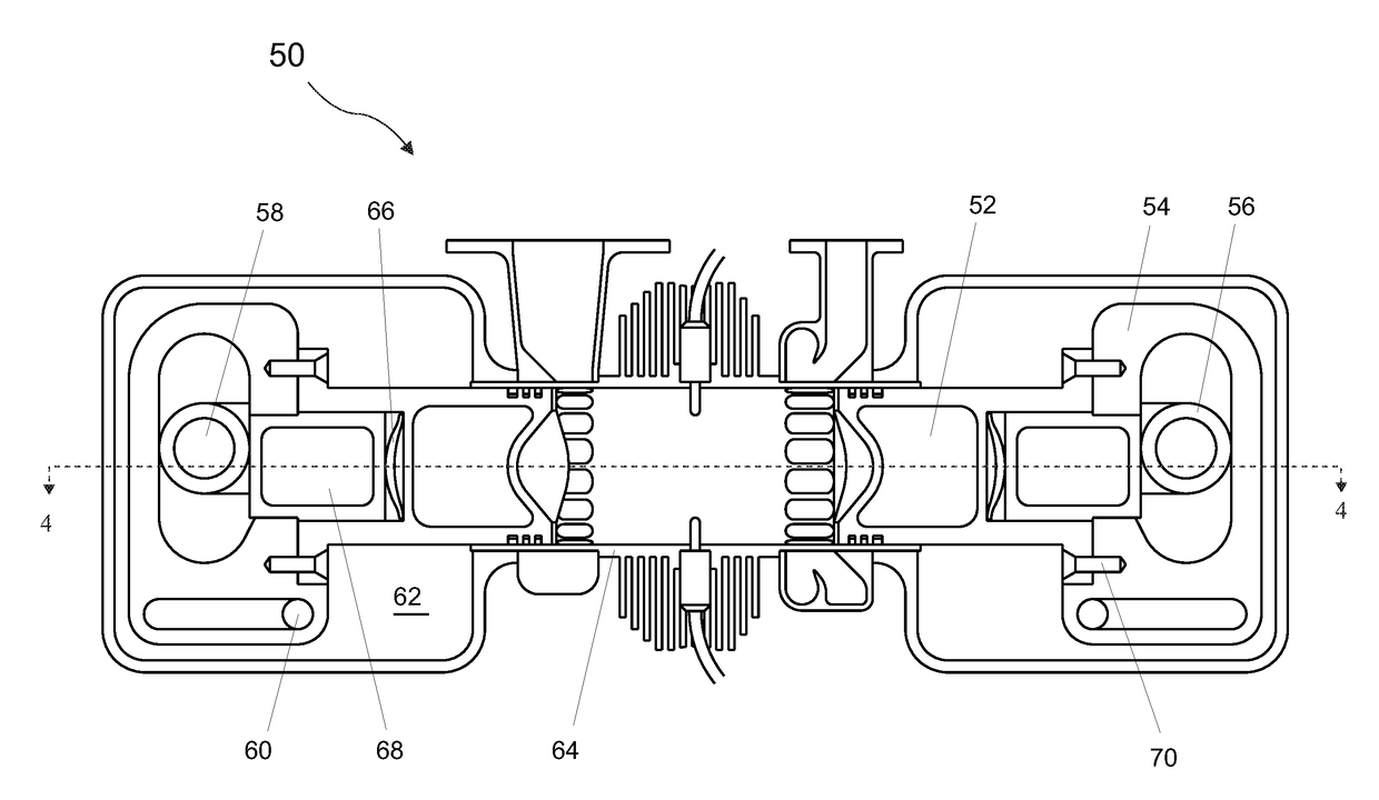
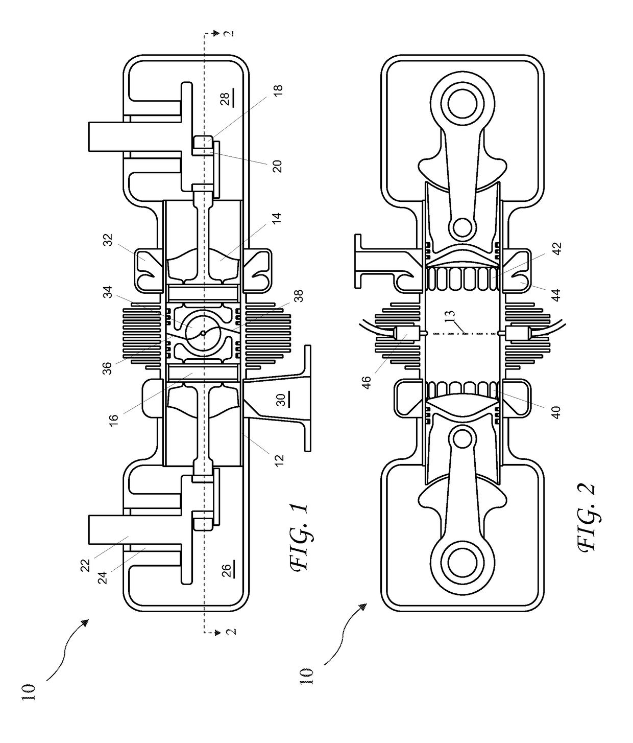
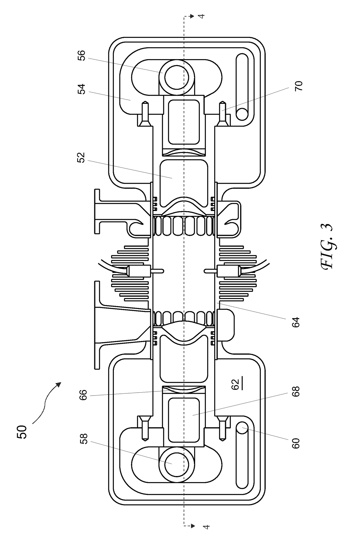
[0035]FIG. 1 is a cross-sectional top view through the center of a first embodiment an internal combustion opposed piston engine 10, viewed from the top, depicting internal parts with pistons 14 at Top Dead Center (TDC). The opposed piston engine 10 has one cylinder 12, two pistons 14 each with a pin 16, two connecting rods 18 each with a journal bearing 20, two crankshafts 22 each with a journal main bearing 24, two crankcases 26 and 28 each securely attached to one of the two different ends of cylinder 12, and an exhaust manifold 30 and an intake manifold 32 each surrounding cylinder 12. The two crankshafts 22 are connected together by gears, ch...


PUM


Abstract

An opposed piston engine includes approximately spherical combustion chamber formed by the two opposed pistons in a single cylinder and an intake manifold including gas hooks. The combustion chamber has a small cone shaped extension on each side leading to each of two opposed injectors located in the cylinder wall where the two pistons meet at the top of their stroke. The combustion chamber configuration reduces the surface area of the chamber and increases the burn length by a significant amount compared to known designs. The gas hooks in the intake manifold restrict the flow of exhaust gases into the intake manifold long enough for the pressure in the cylinder to blow down and the exhaust gasses to attain high velocity passing out through the exhaust manifold, allowing the intake ports to be uncovered before the exhaust ports.

Description

CROSS-REFERENCE TO RELATED APPLICATIONS[0001]The present application claims the priority of U.S. Provisional Patent Application Ser. No. 61 / 935,591 filed Feb. 4, 2014, and is a Continuation In Part of U.S. patent application Ser. No. 14 / 613,247 filed Feb. 3, 2015, which applications are incorporated in its entirety herein by reference.BACKGROUND OF THE INVENTION[0002]The present invention relates in general to opposed piston, direct injected, two strokes per cycle (two stroke), Internal Combustion (IC), opposed piston engines, and more particularly to new, improved technology for design and operation of these types of engines that provides, among other things, higher efficiency, more complete combustion, lower emissions, higher power per unit of displacement, and greater mechanical simplicity than prior art IC engines.[0003]It is well known by those skilled in the art that in a direct injected, state of the art diesel combustion chamber the distance between the tip of the injection ...

Claims


Application Information

Patent Timeline
Patent Type & Authority Applications(United States)
IPC IPC(8): F02B25/08F02B23/06F02B75/28F02B75/02F02B75/32F02M35/10
CPCF02B25/08F02B23/0633F02B75/282F02B75/02F02B75/32F02M35/1019F02B2075/025F01B7/14F02B23/0675F02B25/00Y02T10/12
Inventor HOLLAND, RONALD A.
Owner HOLLAND RONALD A
Why Eureka
Try Eureka