Supercharge Your Innovation With Domain-Expert AI Agents!

Capacitor based power system and unmanned vehicle with the capacitor based power system thereof

a power system and capacitor technology, applied in the field of unmanned aerial vehicles, can solve the problems of high turn-on voltage of diodes, high voltage generation of reverse voltage, damage or destruction of switching elements,

Active Publication Date: 2018-07-19
CAPACITOR SCI
View PDF0 Cites 22 Cited by
  • Summary
  • Abstract
  • Description
  • Claims
  • Application Information

AI Technical Summary

Benefits of technology

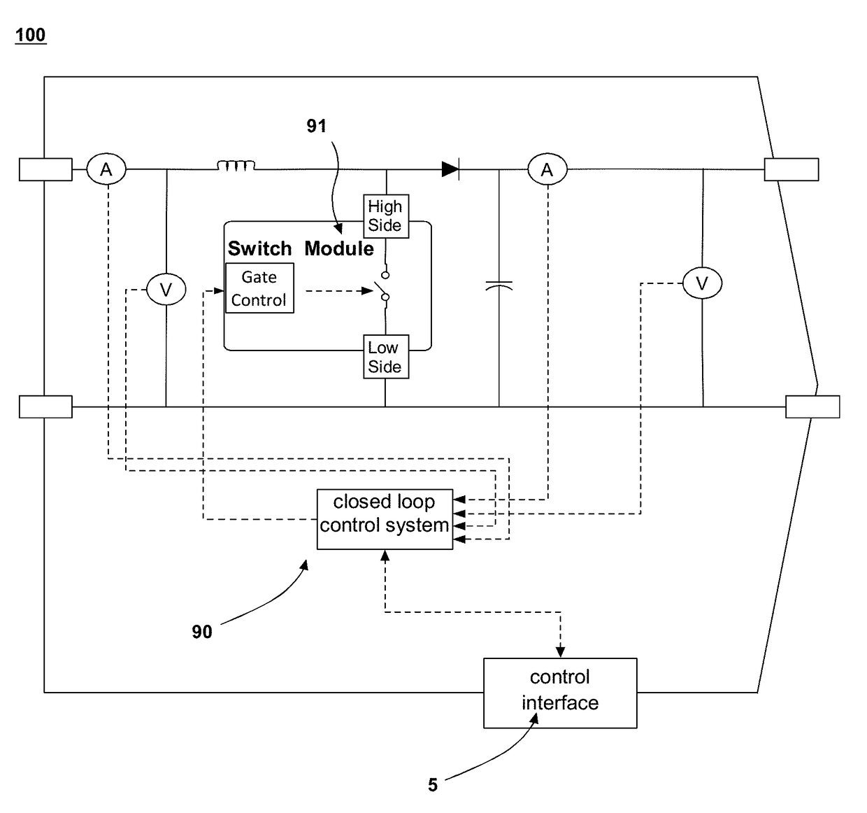
The present patent text describes a power supply system for unmanned vehicles that combines a capacitor energy storage device with a DC-voltage conversion device. This system incorporates the benefits of capacitors (e.g. high power density and quick charging / discharging) while minimizing the disadvantages of batteries (e.g. low power density and hindering operation in harsh environments). The system utilizes metacapacitors, which have greater energy storage capacity than conventional ultracapacitors. The DC-voltage conversion device regulates the voltage on the capacitive energy storage device during charging and discharging. The system is designed to power the unmanned vehicle and can be networked in parallel for increased power capacity. The cells are comprised of a capacitor energy storage device and a DC-voltage conversion device coupled with a capacitor.

Problems solved by technology

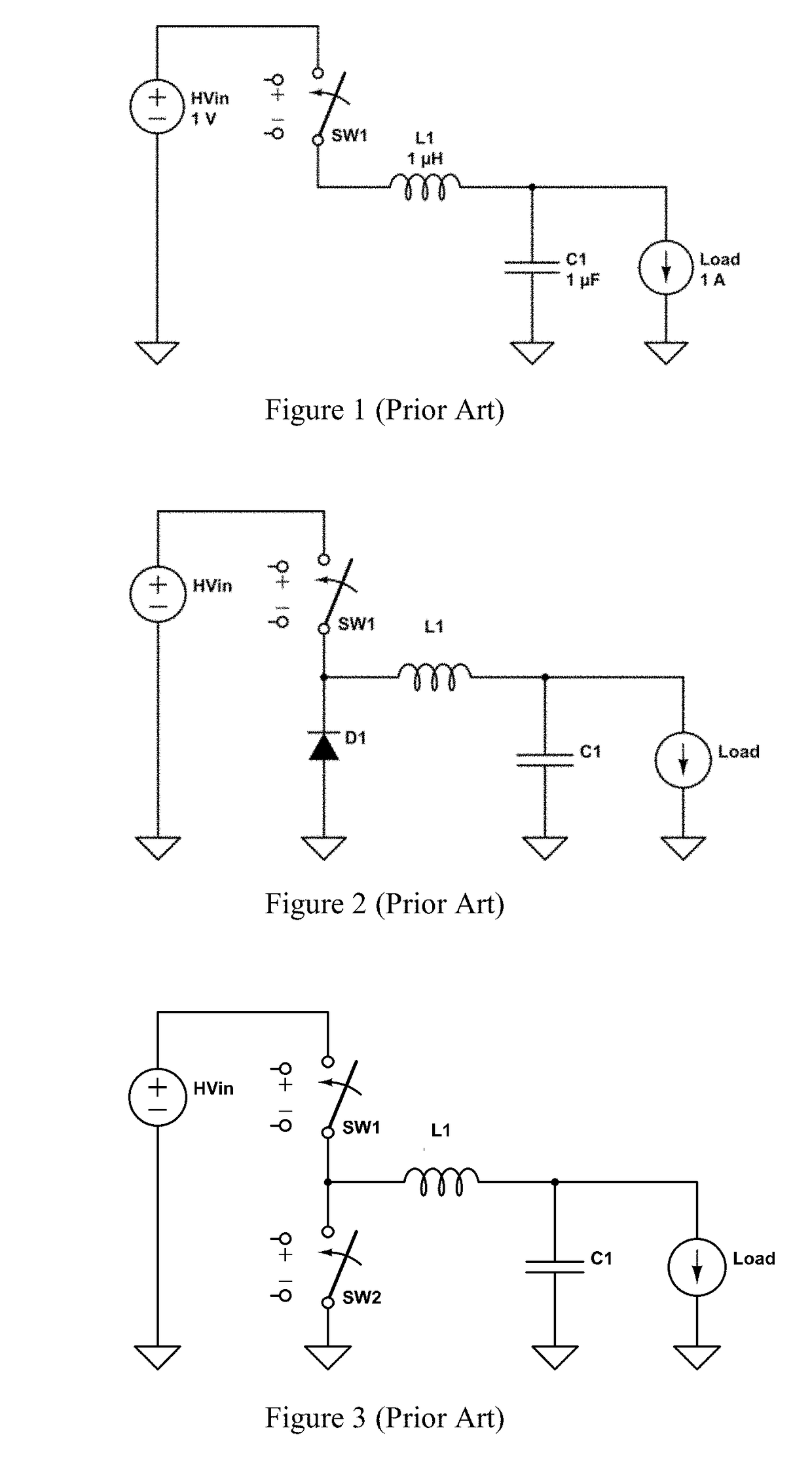
The reverse voltage generated will be extremely high if the incremental change in current di occurs over a sufficiently short increment of time dt, and this may damage or destroy the switching element SW1.
A possible issue with this type of circuit is that the turn-on voltage of the diode needs to be reached and be maintained while the switching element SW1 is turned off and the diode is active.
This means that there will always be a voltage drop of, e.g., ˜0.6V across the diode due to current flowing through it, and therefore a power loss.
Compared to batteries, capacitors are able to store energy with very high power density, e.g. charge / recharge rates, have long shelf life with little degradation, and can be charged and discharged (cycled) hundreds of thousands or millions of times. However, capacitors often do not store energy in small volume or weight as in case of a battery, or at low energy storage cost, which makes capacitors impractical for mass produced aerial vehicles.
Further, due to the internal resistance of batteries power supply systems in unmanned vehicles often suffer from low power density and hinders the unmanned vehicles from operating in harsh environments such as high winds and low and high temperatures.

Method used


Image

  • Capacitor based power system and unmanned vehicle with the capacitor based power system thereof
  • Capacitor based power system and unmanned vehicle with the capacitor based power system thereof
  • Capacitor based power system and unmanned vehicle with the capacitor based power system thereof

Examples


example 1

[0111]

[0112]Synthesis of 3,5-dihydroxybromobenzene: To a 50 mL reaction flask oven dried overnight at 90° C., 3,5-dimethoxybromobenzene (1.012 g, 4.662 mmol) was dissolved in anhydrous CH2Cl2 (8 mL) and placed in an ice water bath to cool for 10 minutes. To this chilled solution, BBr3 (10.2 mmol, 10.2 mL, 1 M in CH2Cl2) was slowly added over 5 minutes. Once this addition was complete, the reaction was removed from the ice water bath and allowed to warm in in air to room temperature and allowed to stir overnight. The reaction was confirmed to be completed after 18 hours by SiO2 TLC using 1:1 Hexanes:EtOAc. The reaction was placed back on an ice water bath to cool for 10 minutes before 1 mL of methanol was added to quench any unreacted BBr3 still present. This reaction mixture was washed with 10 mL of aqueous HCl (2 M) and extracted with EtOAc (3×10 mL). The organic fractions were collected and dried with Na2SO3 before being filtered. The crude reaction mixture was concentrated under ...

example 2

[0142]This Example describes synthesis of one type of Sharp polymer according following structural scheme:

[0143]The process involved in the synthesis in this example may be understood in terms of the following five steps.

a) First Step:

[0144]

[0145]Anhydride 1 (60.0 g, 0.15 mol, 1.0 eq), amine 2 (114.4 g, 0.34 mol, 2.2 eq) and imidazole (686.0 g, 10.2 mol, 30 eq to 2) were mixed well into a 500 mL of round-bottom flask equipped with a bump-guarder. The mixture was degassed three times, stirred at 160° C. for 3 hr, 180° C. for 3 hr, and cooled to rt. The reaction mixture was crushed into water (1000 mL) with stirring. Precipitate was collected with filtration, washed with water (2×500 mL), methanol (2×300 mL) and dried on high vacuum. The crude product was purified by flash chromatography column (CH2Cl2 / hexane=1 / 1) to give 77.2 g (48.7%) of the desired product 3 as an orange solid. 1H NMR (300 MHz, CDCl3) δ 8.65-8.59 (m, 8H), 5.20-5.16 (m, 2H), 2.29-2.22 (m, 4H), 1.88-1.82 (m, 4H), 1.4...

example 3

[0165]Carboxylic acid co-polymer P002. To a solution of 1.02 g (11.81 mmol) of methacrylic acid and 4.00 g (11.81 mmol) of stearylmethacrylate in 2.0 g isopropanol was added a solution of 0.030 g 2,2′-azobis(2-methylpropionitrile) (AIBN) in 5.0 g of toluene. The resulting solution was heated to 80° C. for 20 hours in a sealed vial, after which it became noticeably viscous. NMR shows <2% remaining monomer. The solution was used without further purification in film formulations and other mixtures.


PUM


Abstract

The present disclosure provides an unmanned vehicle comprising a device to be powered; a capacitor energy storage system (CESS) and controller board for at least temporarily powering and operating the device to powered. Further, the CESS includes one or more metacapacitors as an energy storage medium. Additionally, the disclosure provides a capacitor energy storage cell composed of the at least one metacapacitor and a DC-voltage conversion device, where the output voltage of the metacapacitor is the input voltage of the DC-voltage conversion device. Still further, the CESS may be comprised of a module of said capacitor energy storage cells, or a system of modules of said capacitor energy storage cells.

Description

CLAIM OF PRIORITY[0001]This application is a continuation-in-part of U.S. patent application Ser. No. 15 / 043,315 filed Feb. 12, 2016, the entire contents of which are incorporated herein by reference.FIELD OF THE DISCLOSURE[0002]The disclosure relates to an unmanned aerial vehicle having a capacitor energy storage system (CESS) and optionally a connector interface and controller board, the controller board being connected to the CESS, the CESS can discharge and charge through the connector interface, and a DC-voltage conversion device capable of down stepping and up stepping voltage discharge of said CESS to power the controller board and other optional subsystems. An electronic switch can control the power-on and -off of the CESS, thereby avoiding the generation of sparks during the power on process and allowing for the normal use of the capacitor storage unit and the safety of the vehicle.BACKGROUND[0003]Unmanned vehicles such as unmanned aerial vehicles (UAVs) can be used for per...

Claims


Application Information

Patent Timeline
Patent Type & Authority Applications(United States)
IPC IPC(8): H02J7/00H01G4/005H01G4/228H01G4/18B64C39/02
CPCH02J7/0021H01G4/005H01G4/228H01G4/18B64C39/024H02M3/1582H02M3/156H02J7/345H02K11/0094B64C2201/042B64C2201/128B64C2201/027B64C2201/108B64C2201/165B64D27/24B64D2221/00H01G11/56H01G4/14Y02T50/40Y02T50/60H02J7/0014H02J7/0048B64U10/13B64U50/19B64U30/20B64U2101/60
Inventor KELLY-MORGAN, IANLAZAREV, PAVEL IVAN
Owner CAPACITOR SCI
Features
  • R&D
  • Intellectual Property
  • Life Sciences
  • Materials
  • Tech Scout
  • Unparalleled Data Quality
  • Higher Quality Content
  • 60% Fewer Hallucinations
Learn More