
Synchronous rectification module

a rectification module and rectification module technology, applied in the direction of transformer/react mounting/support/suspension, transformer/inductance coil/winding/connection, efficient power electronics conversion, etc., can solve the problem of increasing the loss of lines, reducing the width of the power supply unit, and reducing the power transmission area. the problem of large current, the loss of lines is increased, and the power transmission area is required for a larger current. problem, to achieve the effect of reducing

Active Publication Date: 2018-07-19
DELTA ELECTRONICS (THAILAND) PUBLIC CO LTD
View PDF7 Cites 3 Cited by
  • Summary
  • Abstract
  • Description
  • Claims
  • Application Information

AI Technical Summary

Benefits of technology

The present disclosure provides a synchronous rectification module with high power density. The module is integrated by a transformer, synchronous rectification set, filter circuit, output filter capacitor, output filter inductor, and center tap bus on the same circuit board, saving space, reducing loss, improving efficiency, and achieving miniaturization and high power density. Additionally, the secondary winding of the transformer is constructed by electrically-conductive foil winding and the output of the secondary winding is rectified and connected to the main circuit board through the center tap bus. Furthermore, two transformers are symmetrically disposed on the circuit board and the current-balancing of the two synchronous rectification sets are achieved. The filter capacitors and output filter inductor reduce the path of filtering and enhance the filtering effect. The space between the two transformers is utilized effectively, and the problem of output filtering is also solved.

Problems solved by technology

Thus, in a power supply unit with low-voltage and high current output, the required power transmission area for larger current is regarded as a limitation to reduce the width of the power supply unit.
Consequently, it is difficult to miniaturize the power supply unit and increase the power density.
By utilizing the above output rectifier circuit, the electrically-conductive path of rectification at the secondary side is longer, so that the line loss is increased.
If the layout of components is unreasonable, the rectification effect is affected adversely and the occupied space is increased at the same time.
Consequently, it is difficult to miniaturize the power supply unit and increase the power density.

Method used


Image

  • Synchronous rectification module
  • Synchronous rectification module
  • Synchronous rectification module

Examples


Embodiment Construction

[0021]The present invention will now be described more specifically with reference to the following embodiments. It is to be noted that the following descriptions of preferred embodiments of this invention are presented herein for purpose of illustration and description only. It is not intended to be exhaustive or to be limited to the precise form disclosed.

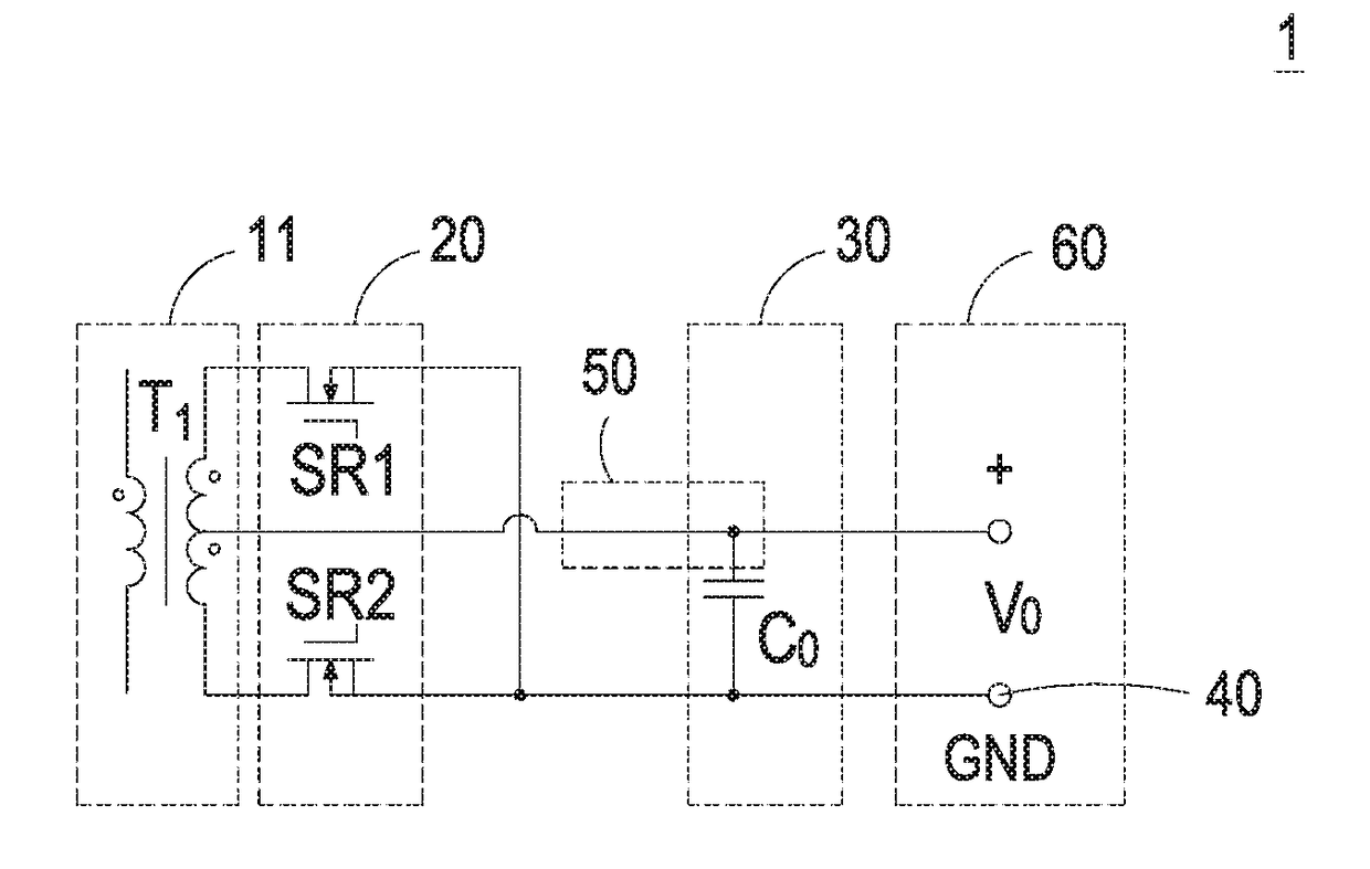
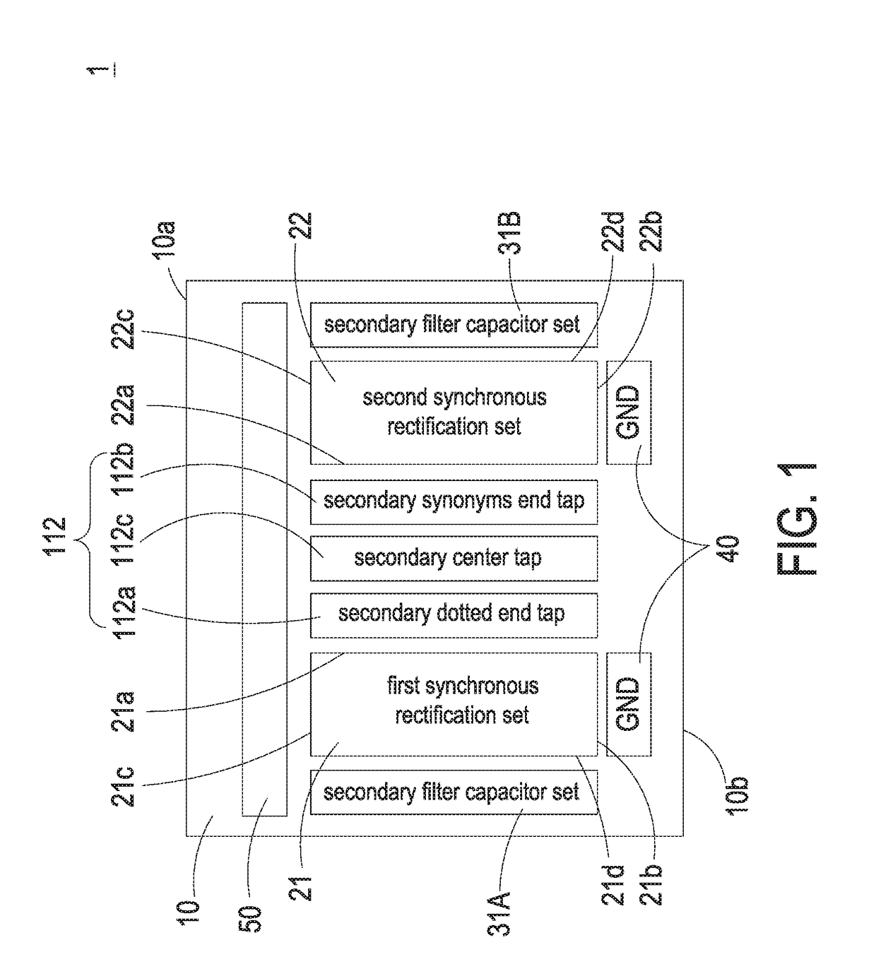
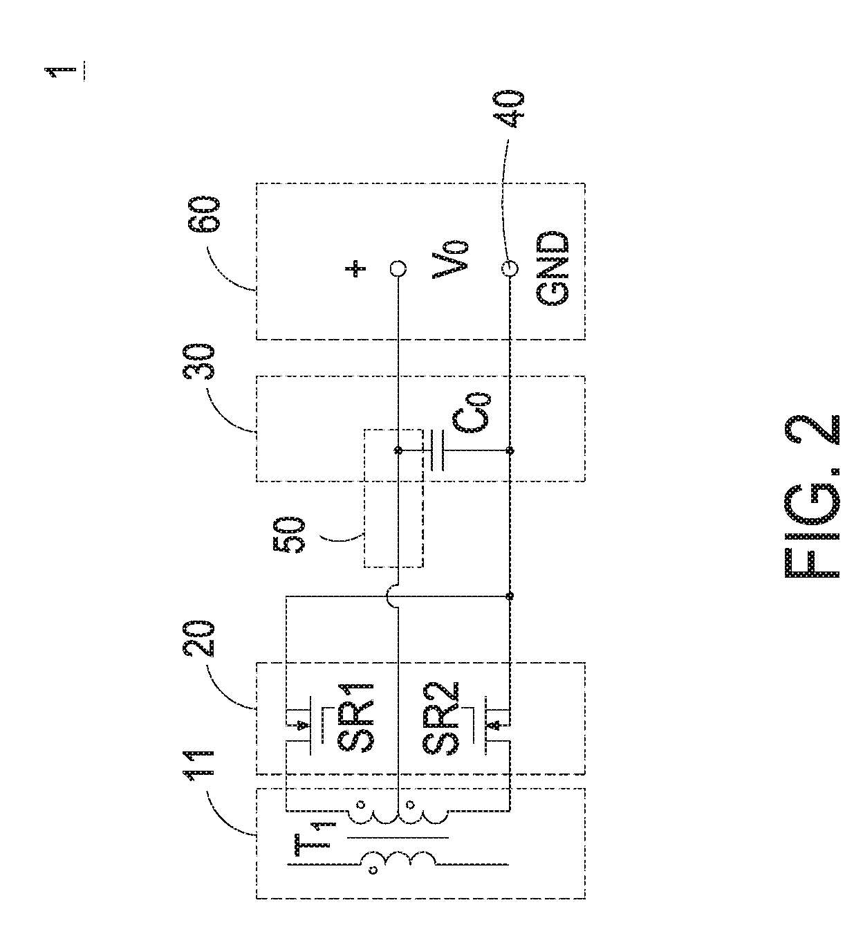
[0022]FIG. 1 is a schematic diagram showing a synchronous rectification module according to a first preferred embodiment of the present invention. FIG. 2 is a circuit topology showing a synchronous rectification module of a preferred embodiment of the present invention. FIGS. 3A and 3B are perspective views showing the structure of the synchronous rectification module of FIG. 1 at different viewing angles. FIG. 3C is a structural exploded view showing the synchronous rectification module of FIG. 1. As shown in FIGS. 1, 2 and 3A to 3C, the synchronous rectification module 1 is configured to output an output voltage V0. The synchro...


PUM


Abstract

The present invention provides a synchronous rectification module. The synchronous rectification module includes a circuit board, a transformer, two synchronous rectification sets and a grounding set. The transformer includes a primary winding and a secondary electrically-conductive foil winding. The first and second synchronous rectification sets are symmetrically disposed on the circuit board, corresponding to the transformer and electrically connected to a secondary dotted end tap and a secondary synonyms end tap of the secondary electrically-conductive foil winding respectively. The secondary electrically-conductive foil winding of the transformer is disposed nearby a lateral edge of the first or second synchronous rectification set, and the grounding set is disposed along a bottom edge of the circuit board and nearby the bottom edge of the first or second synchronous rectification set, so as to reduce the current path of the secondary synchronous rectification circuit and achieve the purposes of miniaturization and high power density.

Description

FIELD OF THE INVENTION[0001]The present invention relates to a synchronous rectification module, and more particularly to a synchronous rectification module having high power density.BACKGROUND OF THE INVENTION[0002]The server power gradually tends to be miniaturized with high power density. In the field of servers, a power system is usually constructed by a rack and plural power supply units accommodated in the rack. If the power system has to increase the output power without changing the width of the original-size rack, more power supply units having smaller widths should be employed. However, the output part of the power supply unit needs enough power transmission area for mounting the output rectification devices including for example the isolation transformer, the rectification device, the filter circuit and the output current path. In addition, the power transmission area is increased in accordance with increase of the output current. Thus, in a power supply unit with low-vol...

Claims


Application Information

Patent Timeline
IPC IPC(8): H02M7/217H01F27/29H01F27/28
CPCH02M7/217H01F27/2847H01F27/29H01F27/06H01F27/40H01F2027/065H01F2027/408H02M1/0048Y02B70/10
Inventor CAI, YOUZHUNYU, CHENGFENGSUN, SANCHAOOUYANG, JIAJIA
Owner DELTA ELECTRONICS (THAILAND) PUBLIC CO LTD
Learn More