
Wearable patch comprising three electrodes for measurement and charging

Inactive Publication Date: 2018-07-26
VIVALNK
View PDF8 Cites 5 Cited by
  • Summary
  • Abstract
  • Description
  • Claims
  • Application Information

AI Technical Summary

Benefits of technology

The patent is about a wearable patch that can be charged wirelessly and controlled to measure different things. It also helps increase the distance the patch can communicate with external devices. This makes it more convenient for people to use and helps gather more data.

Problems solved by technology

As applications and human needs become more sophisticated and complex, electronic patches are required to perform a rapidly increasing number of tasks.
Despite recent development efforts, current wearable patches still suffer several drawbacks: they may not provide adequate comfort for users to wear them; they may not stay attached to user's body for the required length of time; and they are usually not aesthetically appealing.
The conventional wearable patches also include rigid polymer substrates that are not very breathable.
The build-up of sweat and moisture can cause discomfort and irritation to the skin, especially after wearing it for an extended period of time.
Conventional wearable thermometer patches have the additional challenge of inaccurate temperature measurement due to factors such as thermal resistance between the temperature sensor and the human skin, conduction loss of the temperature sensor to the ambient environment, as well as temperature reduction in the user skin caused by the thermal conduction to the wearable patch.
Moreover, conventional wearable thermometer patches can also have slow measurement responses.
Another drawback of some conventional wearable patches is that they contain batteries that are charged by USB cable.
This charging method is inconvenient when the user is not near a power source such as a power outlet or laptop.
Moreover, come conventional wearable patches have limited ranges of wireless communications because their compact sizes usually put constraints on the capacity of the batteries and amplifiers on board.

Method used


Image

  • Wearable patch comprising three electrodes for measurement and charging
  • Wearable patch comprising three electrodes for measurement and charging
  • Wearable patch comprising three electrodes for measurement and charging

Examples


Embodiment Construction

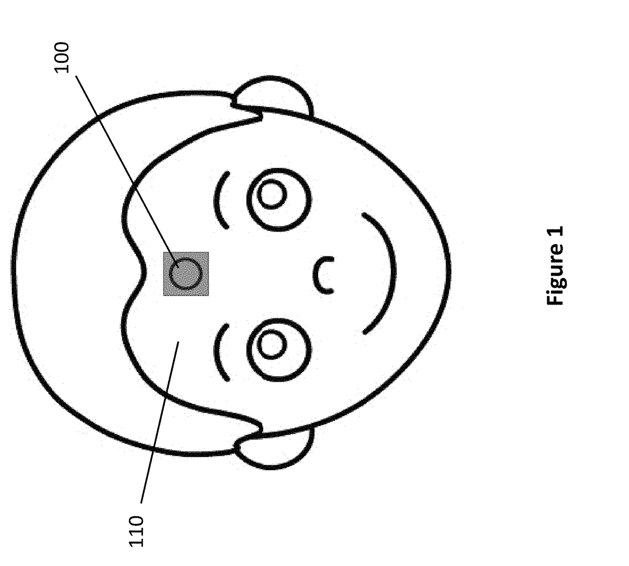
[0029]Referring to FIG. 1, a wearable patch 100 is attached to a user's skin 110 for measuring body vital signs. The wearable patch 100 can be placed on forehead, hand, wrist, arm, shoulder, waist, leg, foot, armpit, or other parts of the body. In the present disclosure, the term “wearable patch” can also be referred to as “wearable sticker” or “wearable tag”.

[0030]As discussed above, wearable electronic patches face several challenges: the user's skin 110 may interfere with their proper operations. For example, the wearable patch 100 may include an antenna for wireless communications with other devices. The antenna's communication range can be significantly reduced when an antenna is placed in contact with the user's skin 110.

[0031]The presently disclosed wearable patch and system aim to overcome the drawbacks in conventional wearable patches, and to provide highly stretchable, compliant, durable, breathable, and comfortable wearable electronic patches while performing more accurat...


PUM


Abstract

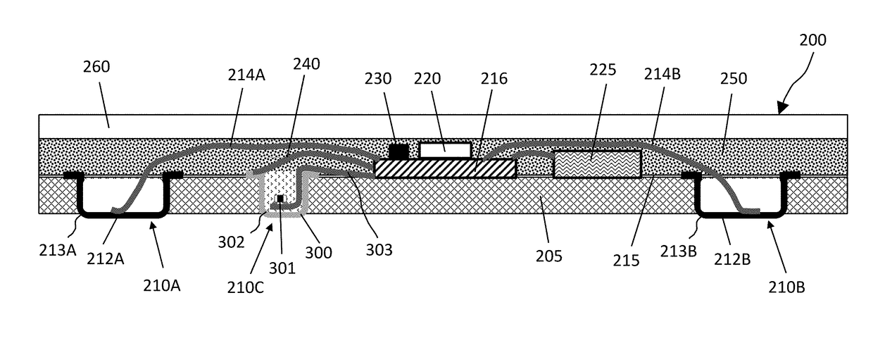
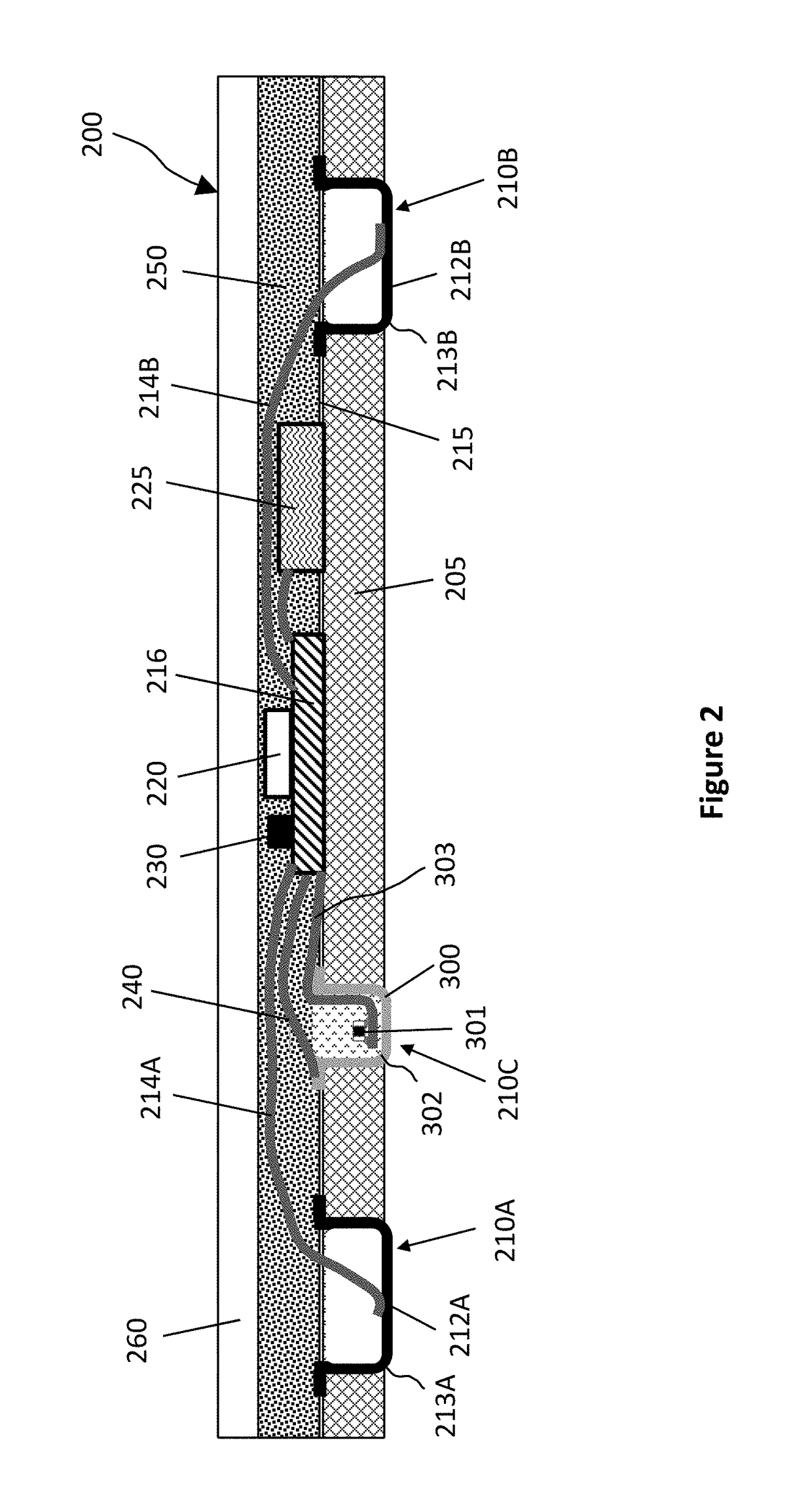
A wearable patch includes a stretchable and permeable substrate, a temperature sensing unit mounted in the stretchable and permeable substrate, wherein the temperature sensing unit includes a first electrode configured to contact a user's skin, and a temperature sensor in thermal contact with the temperature sensor and configured to measure the user's skin temperature. The wearable patch includes a second electrode and a third electrode respectively attached to the stretchable and permeable substrate, a circuit substrate on the stretchable and permeable substrate, and a battery configured to supply power to the control circuit and the temperature sensor. The control circuit can select a first mode for measuring a user's skin temperature and a second mode for charging the battery by the charging station via the first electrode, the second electrode, and the third electrode.

Description

CROSS-REFERENCE TO RELATED APPLICATIONS[0001]The present application is also related to commonly assigned pending U.S. patent application Ser. No. 29 / 562,296, titled “Wearable thermometer having three electric pads”, filed by the same inventors on Apr. 25, 2016, and commonly assigned pending U.S. patent application Ser. No. 29 / 562,367, titled “Wearable thermometer having three electric pads”, filed by the same inventors on Apr. 25, 2016. The disclosures of the above applications are incorporated herein by reference.BACKGROUND OF THE INVENTION[0002]The present application relates to electronic devices, and in particular, to wearable patches that can attach to human skin for conducting measurement.[0003]Electronic patches can be used for tracking objects and for performing functions such as producing sound, light or vibrations, and so on. As applications and human needs become more sophisticated and complex, electronic patches are required to perform a rapidly increasing number of tas...

Claims


Application Information

Patent Timeline
IPC IPC(8): A61B5/01A61B5/00H02J7/00
CPCA61B5/01A61B5/6832A61B5/0008A61B2562/0276H02J7/0054A61B2560/0214A61B2562/164H02J7/0045H02J7/342A61B5/282A61B5/291A61B5/296H02J50/80H02J2310/23
Inventor WANG, ZHIGANGLI, JIANG
Owner VIVALNK
Learn More