Drape attachment to sterile adapters for use in a robotic surgical system

a robotic surgical system and adapter technology, applied in the field of sterile adapters, can solve the problems that the motor, encoder, sensor, etc., cannot be sterilized using conventional sterilization methods such as heat, and the various components of the robotic surgical system cannot. achieve the effect of preventing the sterile adapter and facilitating the decoupling of the fram

Active Publication Date: 2018-07-26
VERB SURGICAL INC
View PDF2 Cites 17 Cited by
  • Summary
  • Abstract
  • Description
  • Claims
  • Application Information

AI Technical Summary

Benefits of technology

[0010]The frame of the sterile adapter may, in other variations, include a body configured to be interposed between a tool driver and a portion of a surgical tool, and a mount projecting from the body for receiving the portion of the surgical tool. The body of the frame may include a first end and a second end opposite the first end, where in some variations an engagement feature may be disposed on the first end of the body for coupling to a first portion of the surgical tool overhanging the body and / or a platform mount may project (e.g., perpendicularly) from the second end of the body for receiving a second portion of the surgical tool. A movable locking member may be included in the sterile adapter and be selectively operable between an engaged position in which the locking member secures a coupling of the frame to the tool driver and a disengaged position in which the locking member facilitates a decoupling of the frame from the tool driver. For example, in some variations, the disengaged position may be blocked when the portion of the surgical tool is received in the mount, thereby substantially preventing the sterile adapter from decoupling from the tool driver when the surgical tool is received in the mount.

Problems solved by technology

However, various components (e.g., motors, encoders, sensors, etc.) of the tool driver and other aspects of the robotic surgical system cannot practically be sterilized using conventional sterilization methods such as heat.

Method used


Image

  • Drape attachment to sterile adapters for use in a robotic surgical system
  • Drape attachment to sterile adapters for use in a robotic surgical system
  • Drape attachment to sterile adapters for use in a robotic surgical system

Examples


Embodiment Construction

[0037]Examples of various aspects and variations of the invention are described herein and illustrated in the accompanying drawings. The following description is not intended to limit the invention to these embodiments, but rather to enable a person skilled in the art to make and use this invention.

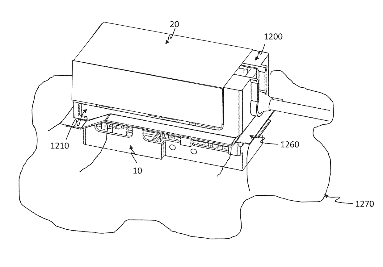
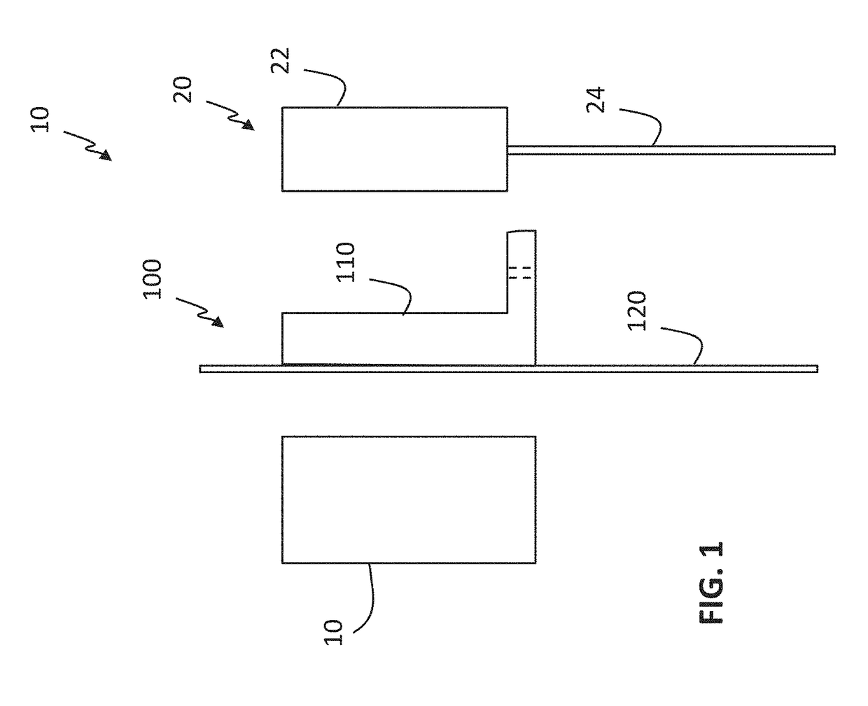
[0038]As shown generally in the schematic of FIG. 1, a portion of a robotic surgical system includes a tool driver 10 configured to actuate a surgical tool 20. One or more drive outputs on the tool driver 10 may, for example, actuate one or more drive inputs on a proximal portion 22 of the surgical tool 20, thereby causing movement (e.g., grasping, cutting, etc.) of an end effector located at a distal end of tool shaft 24. Additionally, a sterile barrier 100 may be placed between the tool driver 10 and the surgical tool 20, forming a barrier between an interior, non-sterile side including the tool driver 10 and an exterior, sterile side including the surgical tool 20 which may, for exampl...


PUM

PropertyMeasurementUnit
angleaaaaaaaaaa
angleaaaaaaaaaa
angleaaaaaaaaaa

Abstract

Generally, a sterile adapter for use in robotic surgery may include a frame configured to be interposed between a tool driver and a surgical tool, a plate assembly coupled to the frame, and at least one rotatable coupler supported by the plate assembly and configured to communicate torque from an output drive of the tool driver to an input drive of the surgical tool.

Description

CROSS-REFERENCE TO RELATED APPLICATIONS[0001]This application claims priority to U.S. Patent Application Ser. No. 62 / 436,957, filed on Dec. 20, 2016, and to U.S. Patent Application Ser. No. 62 / 436,965, filed on Dec. 20, 2016, and to U.S. Patent Application Ser. No. 62 / 436,974, filed on Dec. 20, 2016, and to U.S. Patent Application Ser. No. 62 / 436,981, filed on Dec. 20, 2016, each of which is hereby incorporated by reference in its entirety.TECHNICAL FIELD[0002]This invention relates generally to robotic surgical systems, and more specifically to new and useful sterile adapters for creating a sterile barrier around portions of a robotic surgical system.BACKGROUND[0003]Minimally-invasive surgery (MIS), such as laparoscopic surgery, involves techniques intended to reduce tissue damage during a surgical procedure. For instance, laparoscopic procedures typically involve creating a number of small incisions in the patient (e.g., in the abdomen), and introducing one or more tools and at le...

Claims


Application Information

Patent Timeline
Patent Type & Authority Applications(United States)
IPC IPC(8): A61B46/10A61B34/30A61B46/00B29C45/00B29C65/02
CPCA61B46/10A61B34/30A61B46/40B29C45/0053B29C65/02B29L2031/7546A61B17/00234A61B34/70A61B34/35A61B90/40A61B90/06B25J15/0466A61B34/74A61B34/25G01V8/16A61B34/76A61B90/361A61B2017/00221A61B2017/00216A61B2017/00115A61B2034/744A61B2090/0813A61B2017/00486A61B2017/00199A61B2017/00207A61B2034/743A61B2017/00876A61B2090/0812A61B2034/302A61B2017/00477A61B2090/0811A61B2017/00203A61B2034/742Y10S901/49Y10S901/41Y10S901/46Y10S901/47A61B90/08
Inventor SCHEIB, CHARLES J.
Owner VERB SURGICAL INC
Why Eureka
Try Eureka