Aircraft comprising a propulsion assembly including a fan on the rear of the fuselage

Active Publication Date: 2018-07-26
SN DETUDE & DE CONSTR DE MOTEURS DAVIATION S N E C M A
View PDF10 Cites 21 Cited by
  • Summary
  • Abstract
  • Description
  • Claims
  • Application Information

AI Technical Summary

Benefits of technology

[0014]This configuration also allows the hot gas flows from the two gas generators to mix, which occurs upstream of the power turbine before supplying the power turbine. This prior mixing is a factor for homogenising the circumference of the flow to allow the power turbine to operate in aerodynamic conditions that are similar to those of conventional turbines. This therefore allows the efficiency and the lifetime of the power turbine to be improved.
[0015]It should be noted that this solution differs from that disclosed in patent EP 1267064 in the name of the present applicant, which relates to an engine that has a variable configuration and nominally alternates between subsonic and supersonic operation, the aim of the invention being to provide a remedial device in the event of a malf

Problems solved by technology

This solution ensures that the gas generators are positioned far enough away from the fuselage so that their air intake ducts are spaced apart from the fuselage and do not ingest this boundary layer, which is detrimental to the thermal efficiency of the turbine engine, and

Method used


Image

  • Aircraft comprising  a propulsion assembly including a fan on the rear of the fuselage
  • Aircraft comprising  a propulsion assembly including a fan on the rear of the fuselage
  • Aircraft comprising  a propulsion assembly including a fan on the rear of the fuselage

Examples


Embodiment Construction

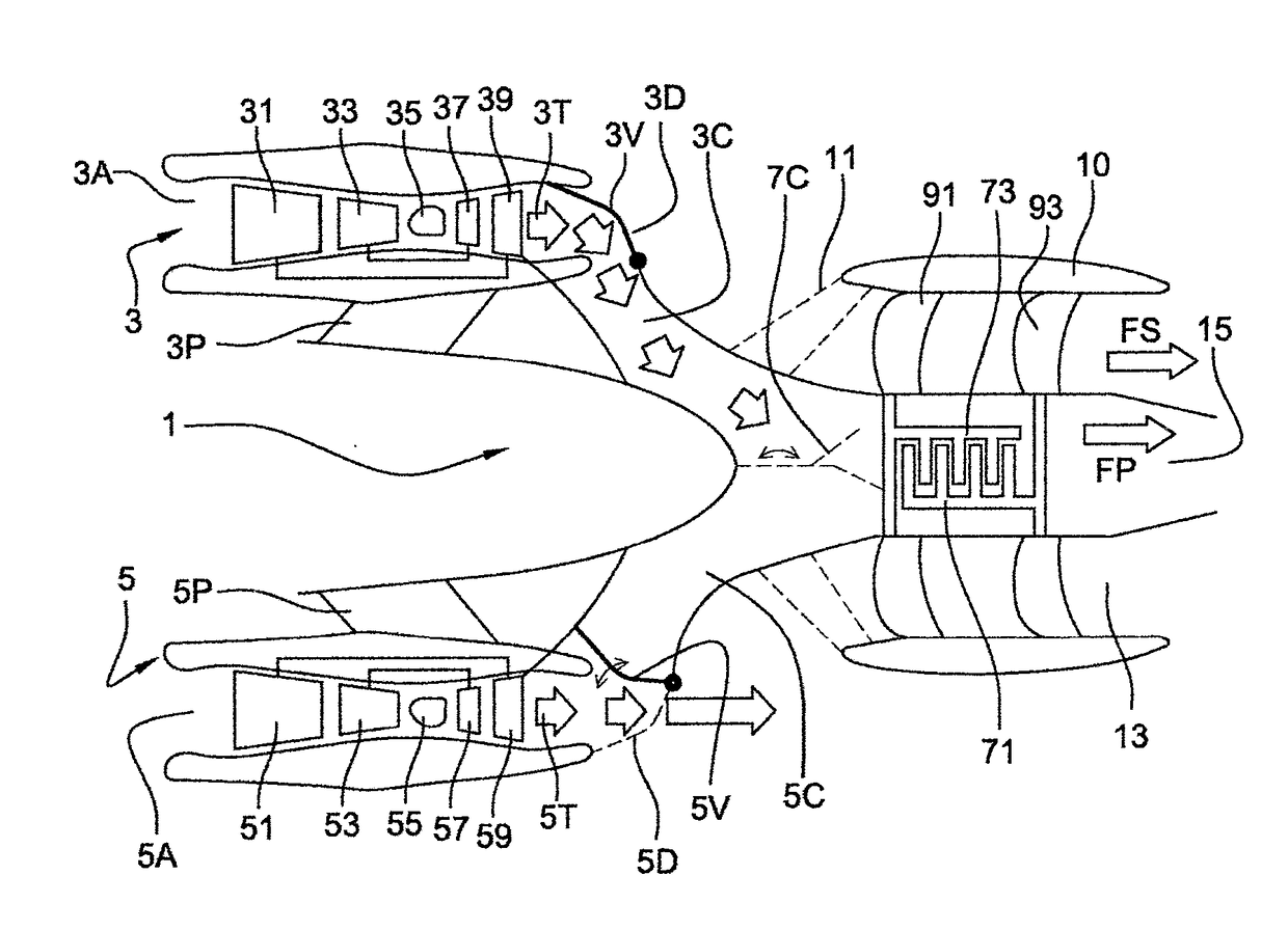
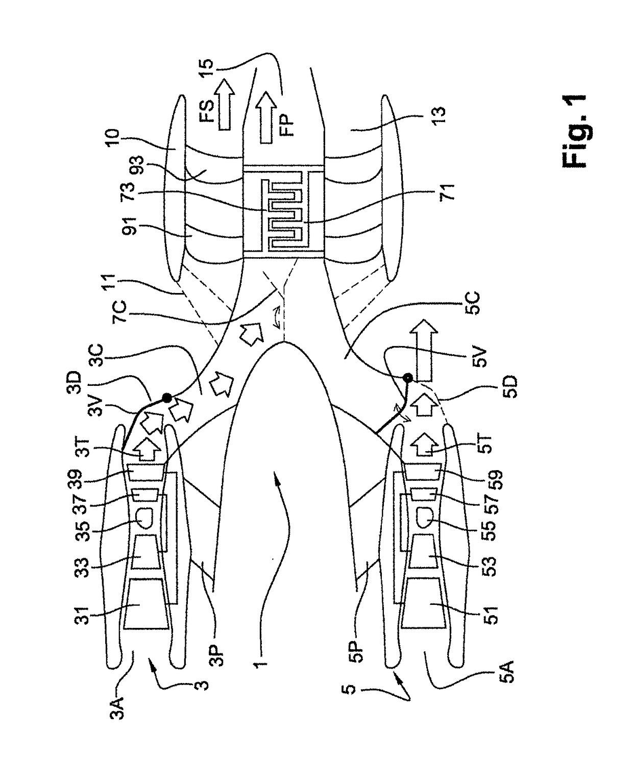
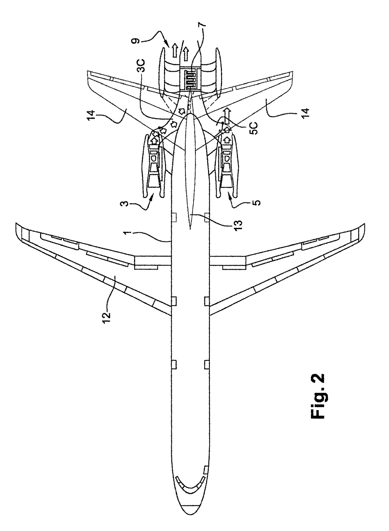
[0031]With reference to FIGS. 1 and 2, the propulsive assembly is mounted at the rear of the aircraft, on the rear part of the fuselage 1. The two gas generators 3 and 5 are mounted on this fuselage along respective axes parallel to that of the fuselage. Each gas generator 3, 5 is mounted on the fuselage so as to have a space between the fuselage and the other gas generator. This space makes it possible to prevent the ingestion of air from the boundary layer formed along the wall of the fuselage. Each gas generator 3, 5 comprises an air intake duct. In this example, each gas generator 3, 5 is respectively mounted on the fuselage by means of struts 3p and 5p. These two struts allow sufficient space to be maintained between the wall of the fuselage and the air intake duct of each of the engines, 3a and 5a, thus preventing the air from the boundary layer from being directed towards the air intake ducts of the gas generators, whilst supplying the fans 91 and 93 of the propulsive unit.

[0...


PUM


Abstract

The present invention relates to an aircraft comprising a fuselage and a thruster downstream of the fuselage. The thruster includes a power turbine, located inside a main flow jet, and at least one fan, located inside a secondary flow jet and mechanically driven by the power turbine. The main flow jet of the power turbine and the secondary flow jet of the fan are concentric. The power turbine is supplied with gases from two gas turbine gas generators via two supply channels. Said aircraft is characterized in that said gas turbine gas generators have axes parallel to that of the fuselage. The air inlet sleeve is spaced apart from the fuselage, and the supply channels each have a hatch for controlling the flow between a position for guiding the gas flow to the power turbine and a position for ejecting the gases into the atmosphere while bypassing the power turbine.

Description

FIELD OF THE INVENTION[0001]The present invention relates to the field of aeronautics in which aircraft are propelled by a set of fan rotors disposed at the rear, in the extension of the fuselage. The fan rotors are driven by free, contra-rotating turbines supplied by gas generators formed by turbojet engines.PRIOR ART[0002]Patent application FR-A1-2997681 proposes a new aircraft architecture that allows noise pollution and aircraft fuel consumption to be reduced while limiting aerodynamic drag.[0003]In such an architecture, an aircraft is propelled by a contra-rotating fan propulsion system integrated into the rear of the fuselage of the aircraft, in the extension thereof. The propulsion system comprises at least two gas generators that supply a power turbine having two contra-rotating rotors for driving two fan rotors, the fans being disposed downstream of the gas generators and being partly supplied by the boundary layer created near the fuselage of the aircraft. The gas generato...

Claims


Application Information

Patent Timeline
IPC IPC(8): B64D27/20B64D33/04F02K3/062F02K3/072F02K3/02B64D35/06F02C6/02B64D27/26
CPCB64D27/20B64D33/04F02K3/062F02K3/072F02K3/025B64D35/06F02C6/02B64D27/26F05D2220/323B64D27/14F01D13/003
Inventor TANTOT, NICOLAS JEROME JEAN
Owner SN DETUDE & DE CONSTR DE MOTEURS DAVIATION S N E C M A
Why Eureka
Try Eureka