Method and System for Optical Three Dimensional Topography Measurement

a three-dimensional topography and optical technology, applied in the direction of instruments, measurement devices, color/spectral properties measurements, etc., can solve the problems of spatial light modulator, oblique projection and oblique imaging cannot be easily implemented, and the optical setup is more complicated and expensive, so as to achieve sufficient in-plane resolution and repeatability, the effect of easy implementation

Active Publication Date: 2018-07-26
KLA TENCOR TECH CORP
View PDF5 Cites 9 Cited by
  • Summary
  • Abstract
  • Description
  • Claims
  • Application Information

AI Technical Summary

Benefits of technology

[0014]It is an object of the invention to provide a method for three-dimensional topography measurement of a surface of an objec...

Problems solved by technology

While confocal microscopy generally provides better height resolution than methods based on structured illumination, it also requires a more complicated and expensive optical setup.
In case of an imaging system with higher NA, above 0.1, neither oblique projection nor oblique imaging is easily implemented, as both depth of focus and working distance are limited.
While the basic concept of structured illumination outlined above and exemplified in the cited patent U.S. Pat. No. 8,649,024 B2 achieves the required ...

Method used


Image

  • Method and System for Optical Three Dimensional Topography Measurement
  • Method and System for Optical Three Dimensional Topography Measurement
  • Method and System for Optical Three Dimensional Topography Measurement

Examples


Embodiment Construction

[0072]Same reference numerals refer to same elements or elements of similar function throughout the various figures. Furthermore, only reference numerals necessary for the description of the respective figure are shown in the figures. The shown embodiments represent only examples of how the invention can be carried out. This should not be regarded as limiting the invention.

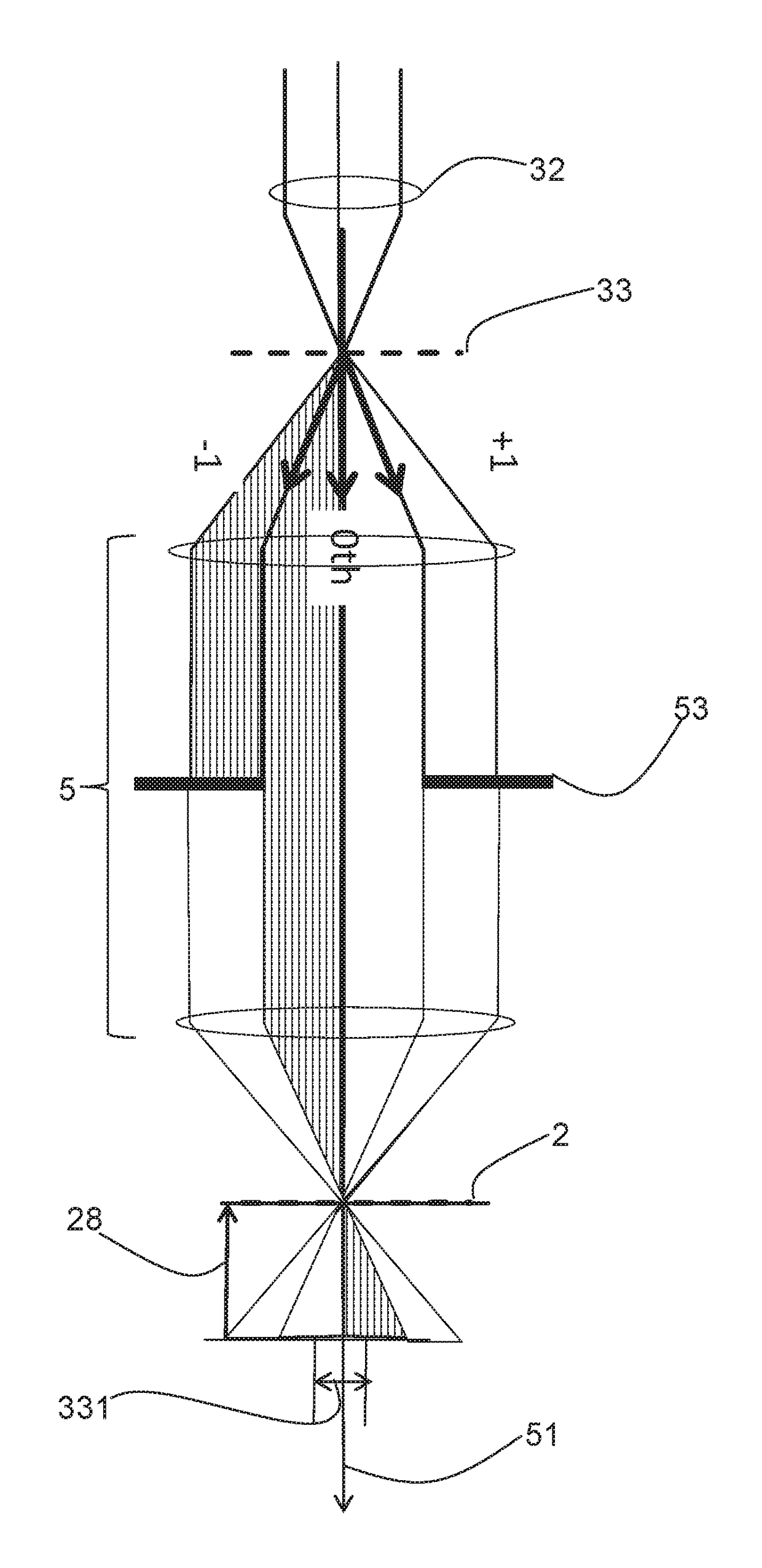
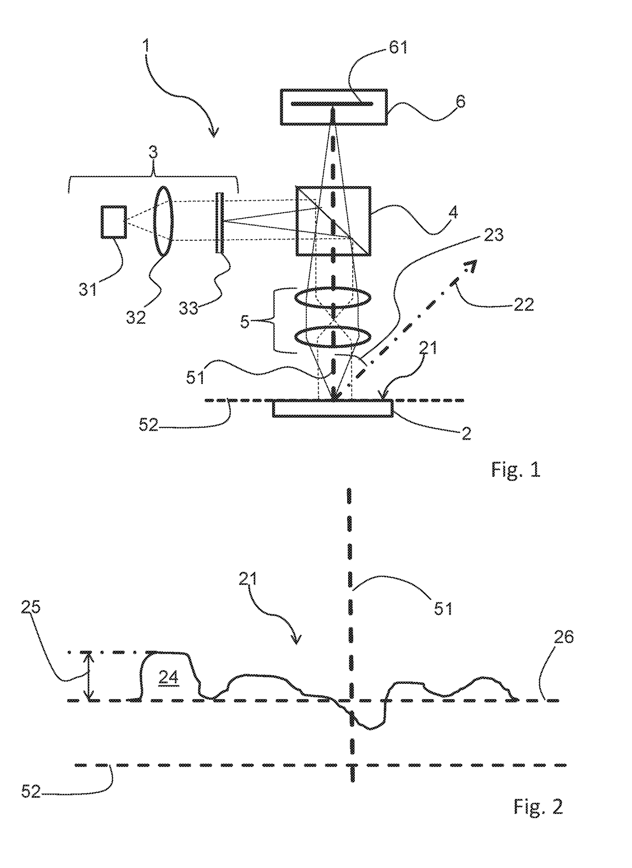
[0073]FIG. 1 shows an embodiment of a system 1 for 3D topography measurements of a surface 21 of an object 2. The system 1 has a source of patterned illumination 3; in the embodiment shown, the source of patterned illumination 3 has a light source 31, for example one or plural LEDs, condenser optics 32, and a pattern mask 33. Patterned illumination of the surface 21 of the object 2 is generated by projecting the pattern mask 33 onto the surface 21. More precisely, in the embodiment shown, light from light source 31, after passing condenser 32 and pattern mask 33, reaches beam splitter 4, which directs at least a p...


PUM


Abstract

For three-dimensional topography measurement of a surface of an object patterned illumination is projected on the surface through an objective. A relative movement between the object and the objective is carried out, and plural images of the surface are recorded through the objective by a detector. The direction of the relative movement includes an oblique angle with an optical axis of the objective. Height information for a given position on the surface is derived from a variation of the intensity recorded from the respective position. Also, patterned illumination and uniform illumination may be projected alternatingly on the surface, while images of the surface are recorded during a relative movement of the object and the objective along an optical axis of the objective. Uniform illumination is used for obtaining height information for specular structures on the surface, patterned illumination is used for obtaining height information on other parts of the surface.

Description

CROSS REFERENCE TO RELATED APPLICATIONS[0001]This application claims priority of US provisional application US 621289,889, filed on Feb. 1st, 2016, which is included herein by reference in its entirety.FIELD OF THE INVENTION[0002]The invention relates to a method and a system for three-dimensional (3D) topography measurement of a surface of an object, wherein patterned illumination is projected onto in the surface of the object through an objective and height information on the surface is obtained from images of the surface recorded during a relative movement between the object and the objective.BACKGROUND OF THE INVENTION[0003]Information on the topography of a surface of an object is required in various areas of is manufacturing. An area where the need for such information is particularly prominent is semiconductor manufacturing, where the semiconductor devices need to be inspected to ensure proper function. Such inspection includes specific structures making up the devices on a w...

Claims


Application Information

Patent Timeline
IPC IPC(8): G01B11/25G01B11/06
CPCG01B11/2518G01B11/2513G01B11/0608G01B2210/56G01B11/2522G01B11/24G01N21/39G01N21/956G02B30/50G01N2021/395
Inventor ZHAO, GUOHENGVAN DER BURGT, MAARTENLIU, SHENGHILL, ANDYDE GREEVE, JOHANVAN GILS, KAREL
Owner KLA TENCOR TECH CORP
Why Eureka
Try Eureka