Illuminator and projector

Active Publication Date: 2018-07-26
SEIKO EPSON CORP
View PDF3 Cites 9 Cited by
  • Summary
  • Abstract
  • Description
  • Claims
  • Application Information

AI Technical Summary

Benefits of technology

This patent describes an illuminator that can improve how evenly it spreads light across a large area. This improvement can be achieved without adding more parts or making the illuminator bigger. The invention also includes a projector that uses this illuminator.

Problems solved by technology

In the light source apparatus described in JP-A-2014-138148, the two multi-lens arrays are required to homogenize the blue light illuminance distribution on the phosphor wheel, resulting in problems of an increase in the number of parts of the light source apparatus, an increase in the size of the light source apparatus, and the like.

Method used


Image

  • Illuminator and projector
  • Illuminator and projector
  • Illuminator and projector

Examples


first embodiment

[0056]A first embodiment of the invention will be described below with reference to FIGS. 1 to 11.

[0057]In the following drawings, components are drawn at different dimensional scales in some cases for clarity of each of the components.

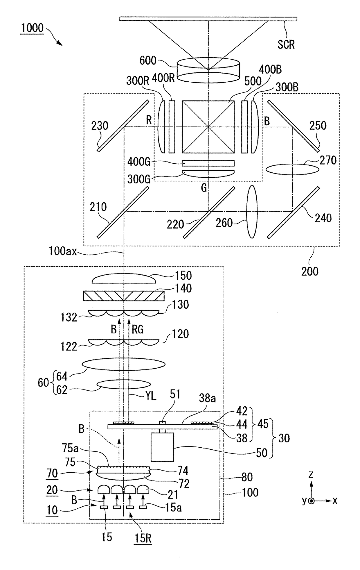
[0058]FIG. 1 shows the optical system of a projector 1000 according to the present embodiment.

[0059]The projector 1000 includes an illuminator 100, a color separation / light guide system 200, light modulators 400R, 400G, and 400B, a cross dichroic prism 500, and a projection system 600, as shown in FIG. 1.

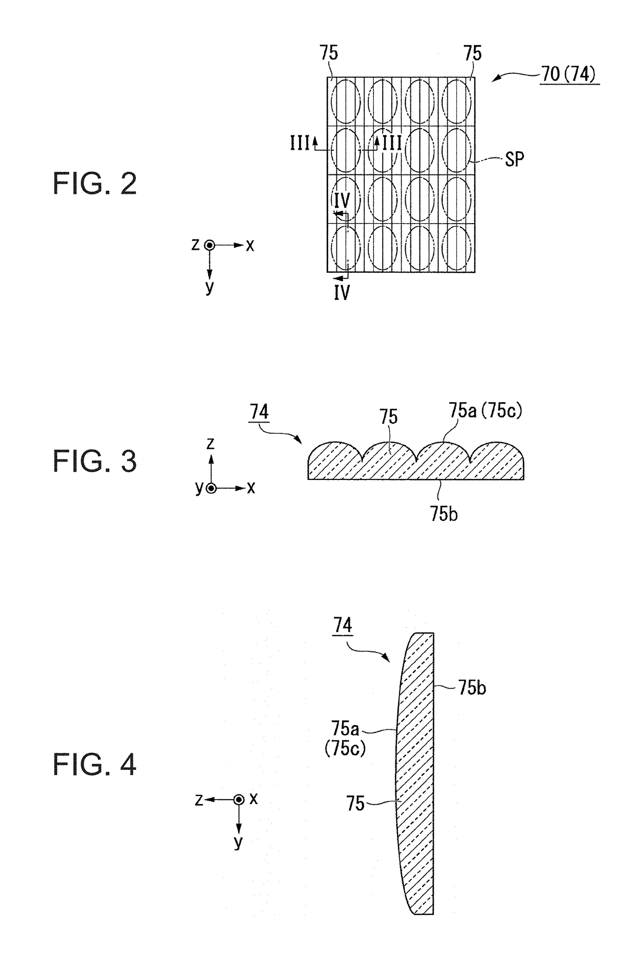
[0060]The illuminator 100 includes a light source apparatus 80, a pickup system 60, a first lens array 120, a second lens array 130, a polarization conversion element 140, and a superimposing lens 150. The light source apparatus 80 includes a light source 10, a collimation system 20, a light forming system 70, and a wavelength conversion element 30.

[0061]The light source 10 emits blue light B. A phosphor layer 42 converts part of the blue light B emit...

second embodiment

[0123]A second embodiment of the invention will be described below with reference to FIG. 12.

[0124]The basic configuration of a projector according to the second embodiment is the same as that in the first embodiment, but the configuration of the illuminator differs from that in the first embodiment.

[0125]FIG. 12 is a schematic configuration diagram of a projector 2000 according to the second embodiment.

[0126]In FIG. 12, the components common to those in the drawings used in the first embodiment have the same reference characters and will not be described.

[0127]An illuminator 700 includes the light source 10, the collimation system 20, a light forming system 85, a first retardation film 91, a light separation element 92, a second retardation film 93, a wavelength conversion element 94, and a diffuser / reflector 95. The light forming system 85 includes a lens array 78, a first light collecting system 111, and a second light collecting system 112. The first light collecting system 111 ...


PUM


Abstract

An illuminator includes a light source, a collimation system on which a light beam flux emitted from the light source is incident, and a light forming system including a lens array including a plurality of lenses. The plurality of lenses each have a lens surface having a non-rotationally symmetric free-form surface. The light forming system is configured to cause the plurality of lenses to divide the light beam flux having passed through the collimation system into a plurality of sub-light beam fluxes and the plurality of sub-light beam fluxes to be incident on an illuminated area.

Description

BACKGROUND1. Technical Field[0001]The present invention relates to an illuminator and a projector.2. Related Art[0002]As an illuminator used in a projector and other apparatus, there has been a proposed illuminator in which a phosphor is irradiated with excitation light emitted from a semiconductor laser or any other excitation light source and fluorescence generated by the phosphor is used.[0003]JP-A-2013-120250 discloses a light source unit including an excitation light source, a phosphor, a diffuser plate disposed between the excitation light source and the phosphor, and alight collecting lens disposed in the vicinity of the phosphor. In the light source unit, excitation light from the excitation light source is diffused by the diffuser plate, and the phosphor is irradiated with the diffused excitation light. The diffuser plate, which diffuses the excitation light, can lower the power density of the excitation light with which the phosphor is irradiated. Lowering the power densit...

Claims


Application Information

Patent Timeline
IPC IPC(8): G03B21/20G02B5/02G02B5/30H01S5/02F21V13/04F21V5/00G02B19/00G02B27/09G02B3/00H04N9/31
CPCG02B19/0004G02B19/0057G02B27/0905G02B3/0062F21V5/007H04N9/3102G02B5/02G02B5/30H01S5/02F21V13/04G03B21/2013G02B26/008G02B27/149G02B27/286G02B27/30G02B19/0014H04N9/3105H04N9/3152H04N9/3158G03B21/208H01S5/0087H01S5/4087H01S5/0071H01S5/4093
Inventor SAKATA, HIDEFUMI
Owner SEIKO EPSON CORP
Why Eureka
Try Eureka