Catheter electrodes for energy management

Active Publication Date: 2018-08-02
MEDTRONIC INC
View PDF6 Cites 63 Cited by
  • Summary
  • Abstract
  • Description
  • Claims
  • Application Information

AI Technical Summary

Benefits of technology

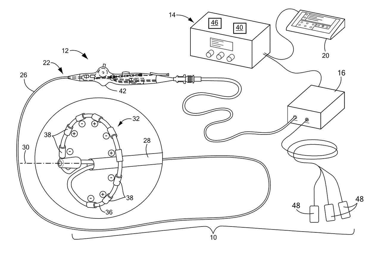
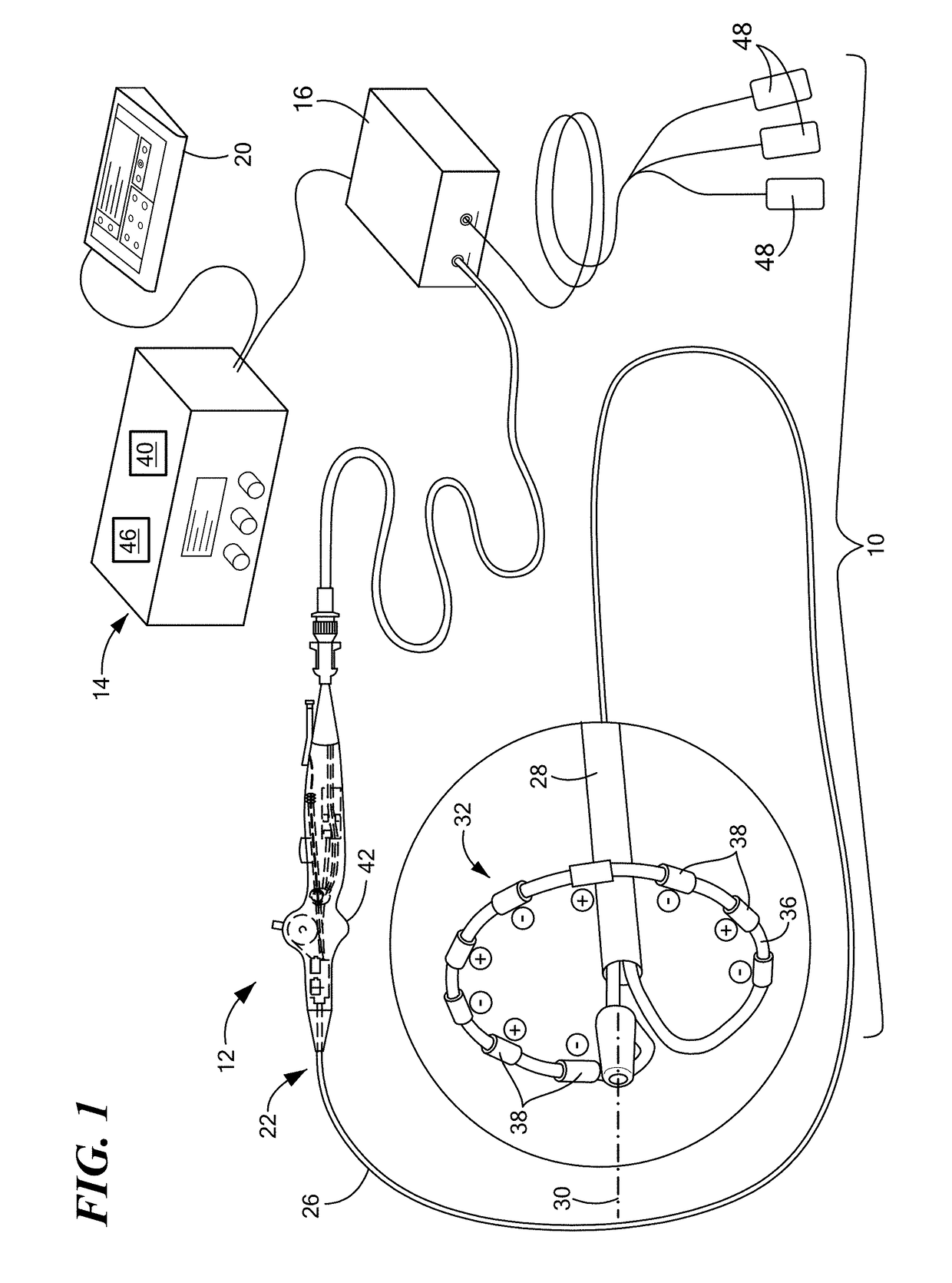
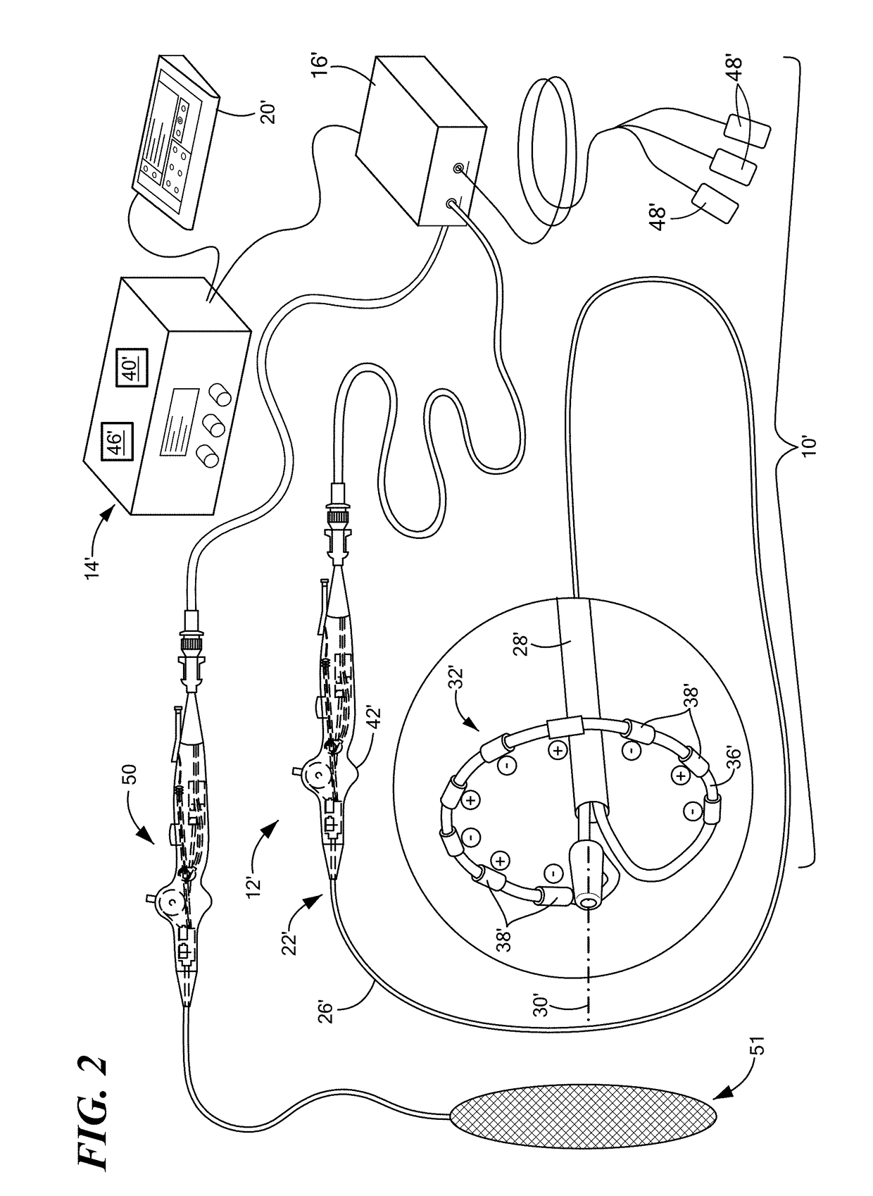
[0006]The present invention advantageously provides methods, systems, and devices for enhancing the efficiency and efficacy of ablation energy delivery and tissue depolarization and voltage mapping. In one embodiment, a system for the delivery of ablation energy may include a medical device configured to ablate and map tissue, the medical device including a treatment element having a plurality of electrodes, the electrodes being arranged in a plurality of pairs of a first electrode and a second electrode, the first electrode and the second electrode of each electrode pair being separated by

Problems solved by technology

Frequently, intracardiac electrogram mapping signals may be recorded from contact with the cardiac tissue by the electrodes of the ablation device, which may co

Method used


Image

  • Catheter electrodes for energy management
  • Catheter electrodes for energy management
  • Catheter electrodes for energy management

Examples


first embodiment

[0120]Referring now to FIG. 27, a comparison between a currently known ring electrode and a concave electrode is shown. The currently known electrode 38 may be any conventional electrode, such as a ring electrode (for example, as shown in dashed lines in FIG. 27) composed of an electrically conductive material and having a cylindrical shape with an at least substantially circular cross section and at least substantially straight parallel sides. Although the concave electrode 66 may be considered a “ring” electrode in that it may circumscribes or extend all the way around a circumference of the device elongate body 22 or carrier element 36, at least a portion of the electrode 66 may be concave (that is, curving in toward a midpoint within the elongate body 22 or carrier element 36), as shown in FIGS. 27, 28, and 30. As a non-limiting example, the electrode 66 be shaped as a concave cylinder having a first end 68 and a second end 70, and a first diameter at a point between the first e...

second embodiment

[0131]Referring now to FIGS. 37 and 38, a treatment element is shown that includes a plurality of protuberant segments alternating with a plurality of electrodes is shown. Each segment 84 may have a first portion that has a diameter that is substantially the same as that of the elongate body 22 and / or the carrier element 36 and a second portion that includes the protrusion 90. The protrusion 90 may be a ring that extends around at least a portion of the circumference of the elongate body 22 and / or the carrier element 36. In the embodiment shown in FIG. 33, the protrusion 90 may be a ring that extends around at least substantially an entirety of the circumference of the elongate body 22 and / or the carrier element 36. Alternatively, protrusion 90 may include one or more cone-shaped protrusions that are radially located at least partially around the circumference of the cylindrical portion. However, these configurations are merely exemplary and, as discussed above, the protrusions may ...

third embodiment

[0133]Referring now to FIG. 39, a portion of a treatment element including a plurality of electrodes and at least one of an insulated, circumferential protuberant segment is shown. Each segment 84 may include a first protrusion 90a at a first end of the segment, a second protrusion 90b at a second end of the segment opposite the first end, and a length 94 between the first 90a and second 90b protrusions. Each of the first 90a and second 90b protrusions may be immediately adjacent the nearest electrode 38. As a non-limiting example, each of the first 90a and second 90b protrusions may be disk shaped and may encircle the entire circumference of the length 94. As shown in FIG. 39, each protrusion 90a, 90b may have a diameter that is greater than the greatest diameter of the length 94. The length of the segment 84 may provide the desired spacing between adjacent electrodes 38, whereas the protrusions 90a, 90b immediately adjacent the electrodes 38 may cause the tissue to extend into the...


PUM


Abstract

Methods, systems, and devices for enhancing the efficiency and efficacy of energy delivery and tissue mapping. One system includes a treatment element having a plurality of electrodes and an energy generator that is configured to deliver electric energy pulses to the electrodes in a variety of patterns. For example, electrodes may be arranged in closely spaced pairs. The energy generator may deliver mapping energy to each electrode in each pair individually to map tissue and may deliver ablation energy to the electrodes in each pair together, such that each pair is treated like a single electrode, to deliver ablation energy, such as bipolar ablation energy between adjacent pairs. One system includes at least one concave electrode, the configuration of which concentrates the energy and drives it deeper into the tissue. One system includes neutral electrodes between active electrodes, the energy generator selectively coupling the neutral electrodes to alter the ablation pattern.

Description

CROSS-REFERENCE TO RELATED APPLICATION[0001]n / aSTATEMENT REGARDING FEDERALLY SPONSORED RESEARCH OR DEVELOPMENT[0002]n / aTECHNICAL FIELD[0003]The present invention relates to methods, systems, and devices for enhancing the efficiency and efficacy of ablation energy delivery and tissue mapping. In particular, the present invention relates to improved electrodes, electrode configurations, and energy delivery patterns.BACKGROUND[0004]A cardiac arrhythmia is a condition in which the heart's normal rhythm is disrupted. Certain types of cardiac arrhythmias, including ventricular tachycardia and atrial fibrillation, may be treated by ablation (for example, radiofrequency (RF) ablation, pulsed RF ablation, pulsed electric field ablation, cryoablation, or the like). The success of an ablation procedure depends largely on the quality and sufficiency of the lesion(s) created during the procedure. For example, a lesion must be deep enough to destroy the arrhythmogenic tissue or adequately disrupt...

Claims


Application Information

Patent Timeline
IPC IPC(8): A61B18/14A61B5/042A61B34/20A61B5/00
CPCA61B18/1492A61B5/0422A61B2018/1467A61B5/6852A61B2018/00577A61B34/20A61B2018/1407A61B2018/1475A61B2034/2046A61B2018/00839A61B5/287
Inventor HOWARD, BRIAN T.STEWART, MARK T.MIKLAVCIC, DAMIJANPURUSHOTHAMAN, BUSHAN K.STIMACK, JEREMY M.
Owner MEDTRONIC INC
Why Eureka
Try Eureka