
System and methods for improving natural gas usage in steam methane reformers

Active Publication Date: 2018-08-02
LAIR LIQUIDE SA POUR LETUDE & LEXPLOITATION DES PROCEDES GEORGES CLAUDE
View PDF1 Cites 0 Cited by
  • Summary
  • Abstract
  • Description
  • Claims
  • Application Information

AI Technical Summary

Benefits of technology

The present invention is a system and method that helps reduce natural gas consumption in SMRs by preheating PSA off-gas and desulfurizing fuel gas for combustion. This results in more efficient operation of the SMR as the fuel gas is desulfurized, allowing for cooling of the flue gas to a temperature below the dew point of sulfuric acid. This enables recovery of additional low level heat from the flue gas, which previously had gone waste.

Problems solved by technology

If the temperature of the flue gas is below the dew point of sulfuric acid, the equipment used in the low temperature range of the flue gas channel will encounter sulfuric acid corrosion.
This means that the energy of the flue gas below the sulfuric acid dew point is unused.
As such, Grover does not disclose cooling the flue gas to a temperature below the dew point of sulfuric acid, nor is there any discussion of potential problems associated with sulfur formation.
Furthermore, no detailed implementation is disclosed.

Method used


Image

  • System and methods for improving natural gas usage in steam methane reformers
  • System and methods for improving natural gas usage in steam methane reformers
  • System and methods for improving natural gas usage in steam methane reformers

Examples


second embodiment

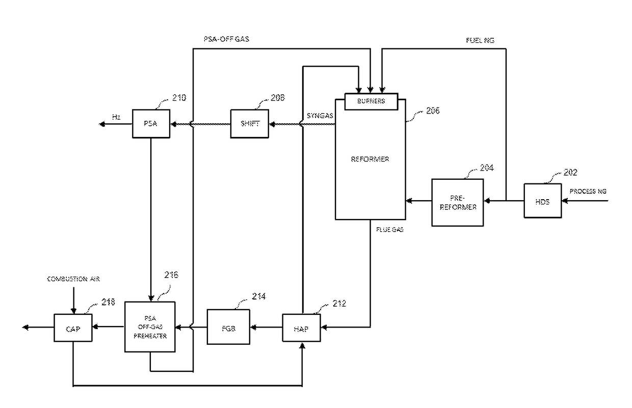
[0055]FIG. 3 illustrates a block flow diagram of an SMR system using one PSA off-gas pre-heater to pre-heat the PSA off-gas of the present invention. The primary difference between the two embodiments illustrated in FIG. 3 and FIG. 2 is PSA off-gas pre-heater 216 is installed downstream of CAP 218 in FIG. 3, rather than upstream of CAP 218. In this embodiment, both process gas and fuel gas are also desulfurized.

third embodiment

[0056]FIG. 4 illustrates a block flow diagram of an SMR system using one PSA off-gas pre-heater to pre-heat the PSA off-gas of the present invention. The primary difference between the two embodiments illustrated in FIG. 4 and FIG. 2 is PSA off-gas pre-heater 216 is installed in parallel with CAP 218 to preheat the PSA off-gas, rather than upstream or downstream of CAP 218. In this embodiment, both process gas and fuel gas are desulfurized, and the flue gas exiting FGB 214 is split into two streams. One stream is used to pre-heat the PSA off-gas from PSA unit 210 in PSA off-gas pre-heater 216 before the PSA off-gas is forwarded to a plurality of burners of reformer 206; the other one is used to pre-heat a clod combustion air with CAP 218. After the PSA off-gas is pre-heated with PSA off-gas pre-heater 216, the temperature of the heated PSA off-gas can be increased up to the temperature of the flue gas downstream of FGB 214. In this embodiment, the temperature of the flue gas downstr...

fourth embodiment

[0057]FIG. 5 illustrates a block flow diagram of an SMR system using two PSA off-gas pre-heaters to pre-heat the PSA off-gas of the present invention. The primary difference between the two embodiments illustrated in FIG. 5 and FIG. 2 is two PSA off-gas pre-heaters (216 and 220) are used, with PSA off-gas pre-heater 216 being upstream CAP 218 and PSA off-gas pre-heater 220 being downstream CAP 218. In this embodiment, PSA off-gas pre-heaters 216 and 220 are installed in series. The PSA off-gas is pre-heated by PSA off-gas pre-heater 220 first and then forwarded to PSA off-gas pre-heater 216 where the PSA off-gas is further pre-heated prior to entering the burners of reformer 206 for use as fuel.


PUM


Abstract

An improved hydrogen generation system and method for using the same are provided. The system includes an HDS unit configured to desulfurize hydrocarbons, a pre-reformer configured to convert heavy hydrocarbons within the process gas stream to methane, a reformer configured to produce a syngas stream and a flue gas, a PSA unit configured to produce a product hydrogen stream and a PSA off-gas stream, and means for cooling the flue gas against a combustion air and the PSA off-gas stream to a temperature below the dew point of sulfuric acid.

Description

TECHNICAL FIELD OF INVENTION[0001]Disclosed are systems and methods for reducing natural gas usage by improving thermal efficiency in steam methane reformers (SMRs) by desulfurizing combustion fuel and preheating a pressure swing adsorption (PSA) off-gas against a sulfur-lean flue gas. In particular, by using desulfurized natural gas as a fuel gas, the temperature of the flue gas to a stack may be lowered without a significant risk of sulfuric acid condensation, and therefore, additional thermal energy from the flue gas may be used to preheat process streams such as the PSA off gas.BACKGROUND OF THE INVENTION[0002]In large scale SMRs, approximately 50% of the thermal energy input into the firebox of a reformer is transferred to SMR reaction tubes and used to provide energy to drive the endothermic steam methane reforming reaction (CH4+H2O+206 kJ / molCO+3H2). Since the reforming reaction is generally carried out at a high temperature, e.g., 750° C. to 950° C., the temperature of a flu...

Claims


Application Information

Patent Timeline
IPC IPC(8): C01B3/36C10L3/10C01B3/56
CPCC01B3/36C10L3/103C01B3/56C01B2203/1258C01B2203/042C01B2203/1241C01B2203/025C01B3/384C01B3/48C01B2203/0233C01B2203/0283C01B2203/043C01B2203/0822C01B2203/0883C01B2203/0894C01B2203/1235C01B2203/127C01B2203/142Y02P20/129Y02P20/10
Inventor KANG, TAEKYUSHRIVASTAVA, SWATANTRA KUMARLEHMANN, MAIK
Owner LAIR LIQUIDE SA POUR LETUDE & LEXPLOITATION DES PROCEDES GEORGES CLAUDE
Learn More