
Flux machine

a technology of electromagnetic motors and generators, applied in the direction of mechanical energy handling, synchronous machines with stationary armatures, rotating magnets, etc., can solve the problems of difficult fabrication and assembly of stator and rotor components

Pending Publication Date: 2018-08-02
CLEARWATER HLDG
View PDF2 Cites 11 Cited by
  • Summary
  • Abstract
  • Description
  • Claims
  • Application Information

AI Technical Summary

Benefits of technology

The patent describes a new type of electric machine that has several advantages over previous designs. It has a high magnetic density and can have a larger number of poles without losing power. This allows for higher power densities. The machine also has a high torque to weight ratio and efficiency. This means it can generate more power with less weight and has lower losses.

Problems solved by technology

Such machines have a three dimensional magnetic circuit which has traditionally made fabrication and assembly of stator and rotor components difficult.

Method used


Image

  • Flux machine
  • Flux machine
  • Flux machine

Examples


Embodiment Construction

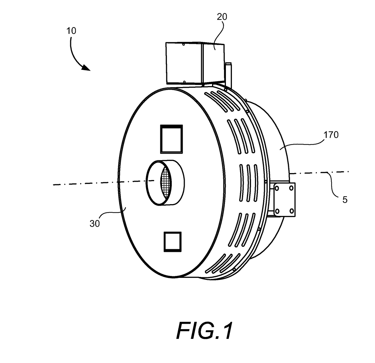
[0015]FIG. 1 shows that machine 10 may be generally circular in shape and relatively short axially between shroud 30 and flywheel housing 170 providing space and weight savings. Electrical connections to machine 10 may be made via a standard connection box 20 and mechanical engagement may be made via one or more coaxial shafts aligned with central axis 5 as shown in the FIGS. 6-9.

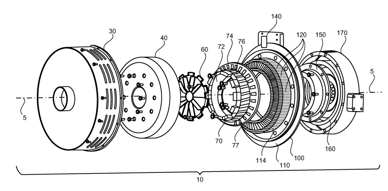
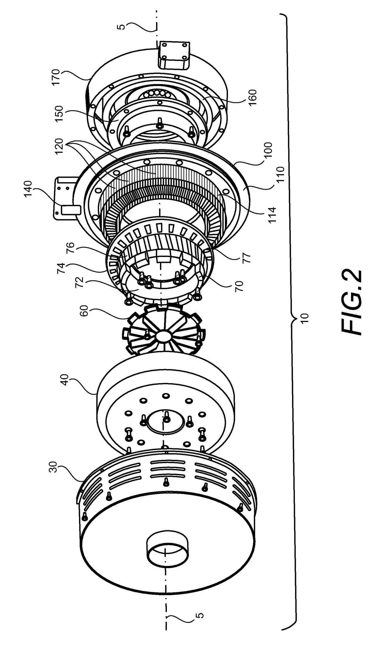
[0016]FIG. 2 illustrates several components and sub-assemblies of machine 10 according to embodiments, showing their relative axial positions. Moving from left to right in FIG. 2, shown are: shroud 30, outer rotor-magnet assembly 40, fan 60, inner rotor-magnet assembly 70, stator assembly 100 with coil assemblies 120, rotor hub 150, flywheel 160, and flywheel housing 170. These components are aligned about common axis 5 which is also the center of rotation of machine 10. In embodiments, outer rotor-magnet assembly 40, fan 60, inner rotor-magnet assembly 70, rotor hub 150, and flywheel 160 may be mutually jo...


PUM


Abstract

A flux machine has plural coil assemblies and plural magnet sets arranged in mutual close proximity and circularly about a central axis. Either one of the coil assemblies and the magnet sets are supported by at least one axle which is aligned with the central axis, and either one of the coil assemblies and magnet sets executes rotary motion about the central axis when electrical current is present in the coil assemblies. Magnetic flux of the magnet sets is directed axially and radially while machine rotation is orthogonal to the direction of flux. A plurality of magnets in each magnet set are supported by one or another of a plurality of coaxially aligned axles so that the flux machine may operate as an electrical motor, as an electrical generator, or both at the same time.

Description

TECHNICAL FIELD[0001]This disclosure relates to rotating electromagnetic motors and generators.BACKGROUND ART[0002]Magnet transverse flux machines conduct magnetic flux perpendicular (transverse) to the current in the coil and can produce higher torque density than standard brushless machines with longitudinal flux. Such machines have high power density and can be used both as motors and generators. Torque increases with the number of poles at a constant stator current. Due to the high number of poles in a transverse flux machines, the frequency of electric current in stator windings is high while shaft speed is low. Such machines have a three dimensional magnetic circuit which has traditionally made fabrication and assembly of stator and rotor components difficult. Prior art methods of manufacturing the magnetic circuits require the formation of individual U-shaped magnetic circuits. For example, a U-shaped magnetic circuit may be comprised of a plurality of individual U-shaped lam...

Claims


Application Information

Patent Timeline
Patent Type & Authority Applications(United States)
IPC IPC(8): H02K21/24H02K7/02H02K16/02H02K51/00
CPCH02K21/24H02K7/02H02K16/02H02K51/00H02K2201/12H02K21/12H02K21/14H02K21/22H02K1/148Y02E10/72Y02T10/64
Inventor NEWMARK, G. NOAHCOLLINS, STEPHEN M.HARWITH, R. MORGAN
Owner CLEARWATER HLDG
Learn More