Temperature sensor and position detection device

Inactive Publication Date: 2018-08-09
ALPS ALPINE CO LTD
View PDF7 Cites 0 Cited by
  • Summary
  • Abstract
  • Description
  • Claims
  • Application Information

AI Technical Summary

Benefits of technology

The patent describes a temperature sensor with improved performance. It achieves this by using a heat insulating section between the temperature sensor element and the retaining portion, which reduces heat dissipation and improves temperature sensing. The heat insulating member is easily arranged and fixed to the wire member, without the need for a biasing mechanism, resulting in improved temperature sensing performance. The heat insulating section also enhances thermal insulation by using a gas that is less heat-transferable. This improved temperature sensor can be used in position detection devices to better control the detection object based on its ambient temperature.

Problems solved by technology

However, detection accuracy of the temperature sensor element degrades if heat dissipates.
However, the above-described related art has a problem that a sensor structure is complicated because of the necessity of the structure for biasing the glass tube 941 toward the tip side by the sealing member 971.

Method used


Image

  • Temperature sensor and position detection device
  • Temperature sensor and position detection device
  • Temperature sensor and position detection device

Examples


first embodiment

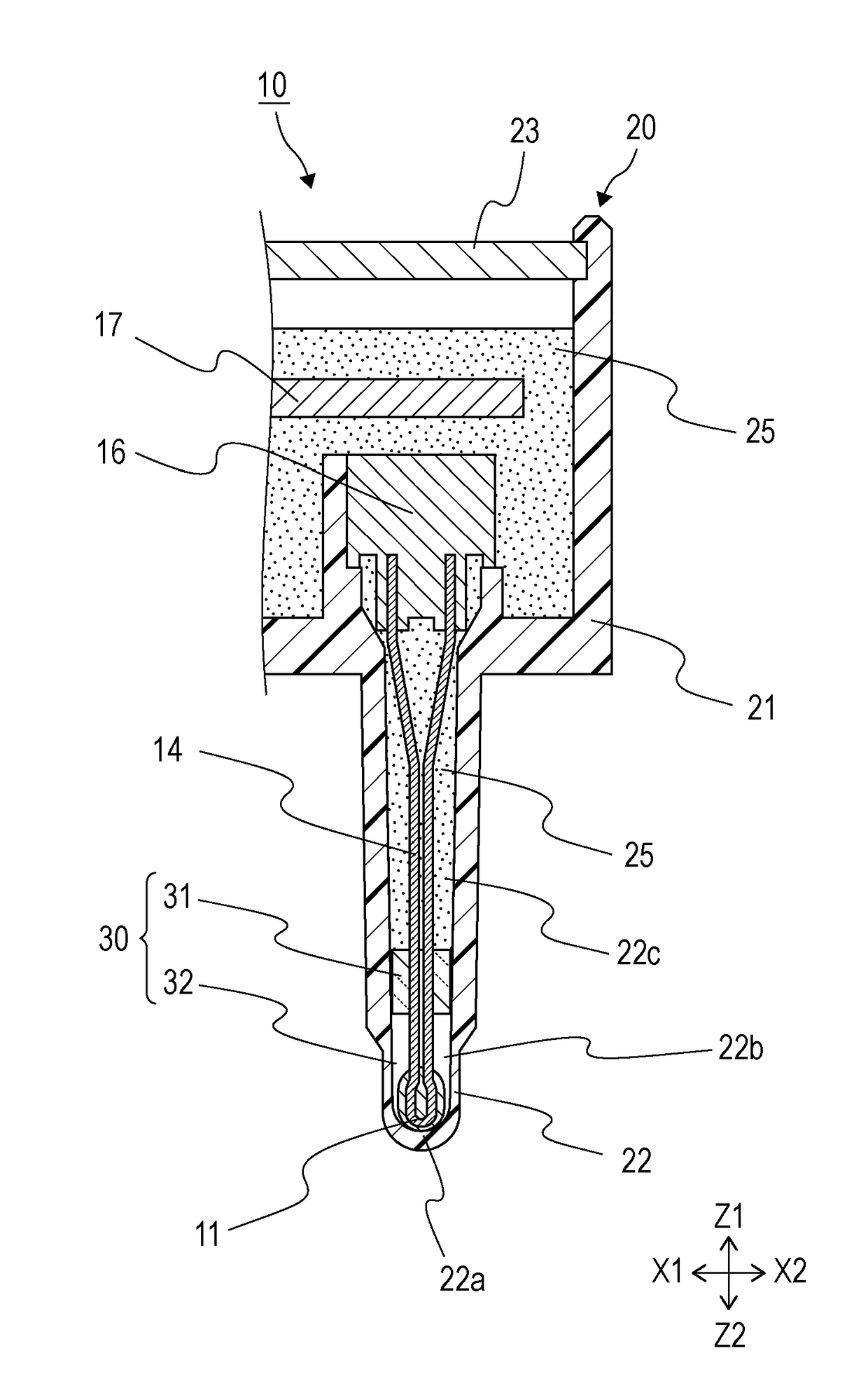
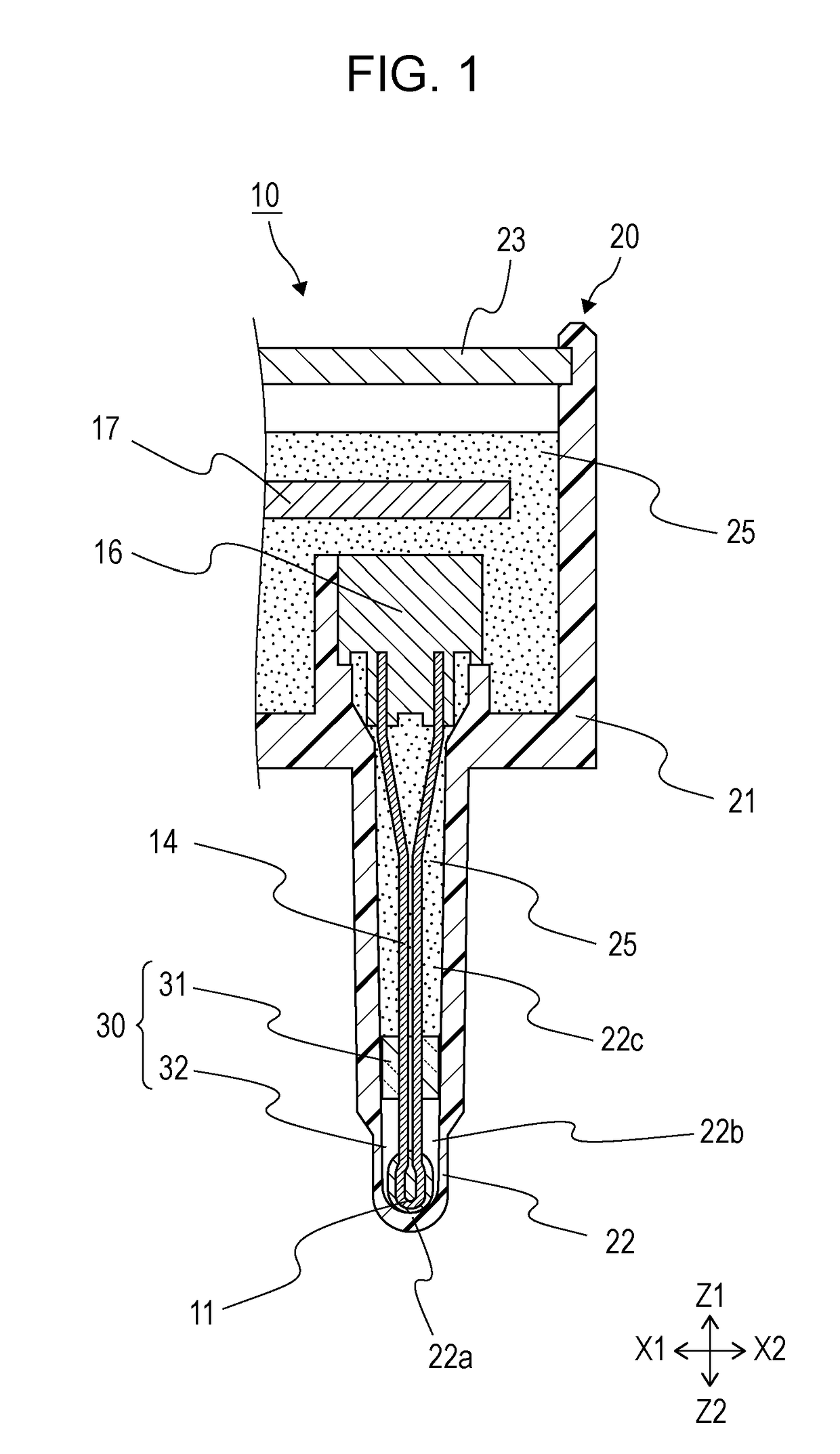
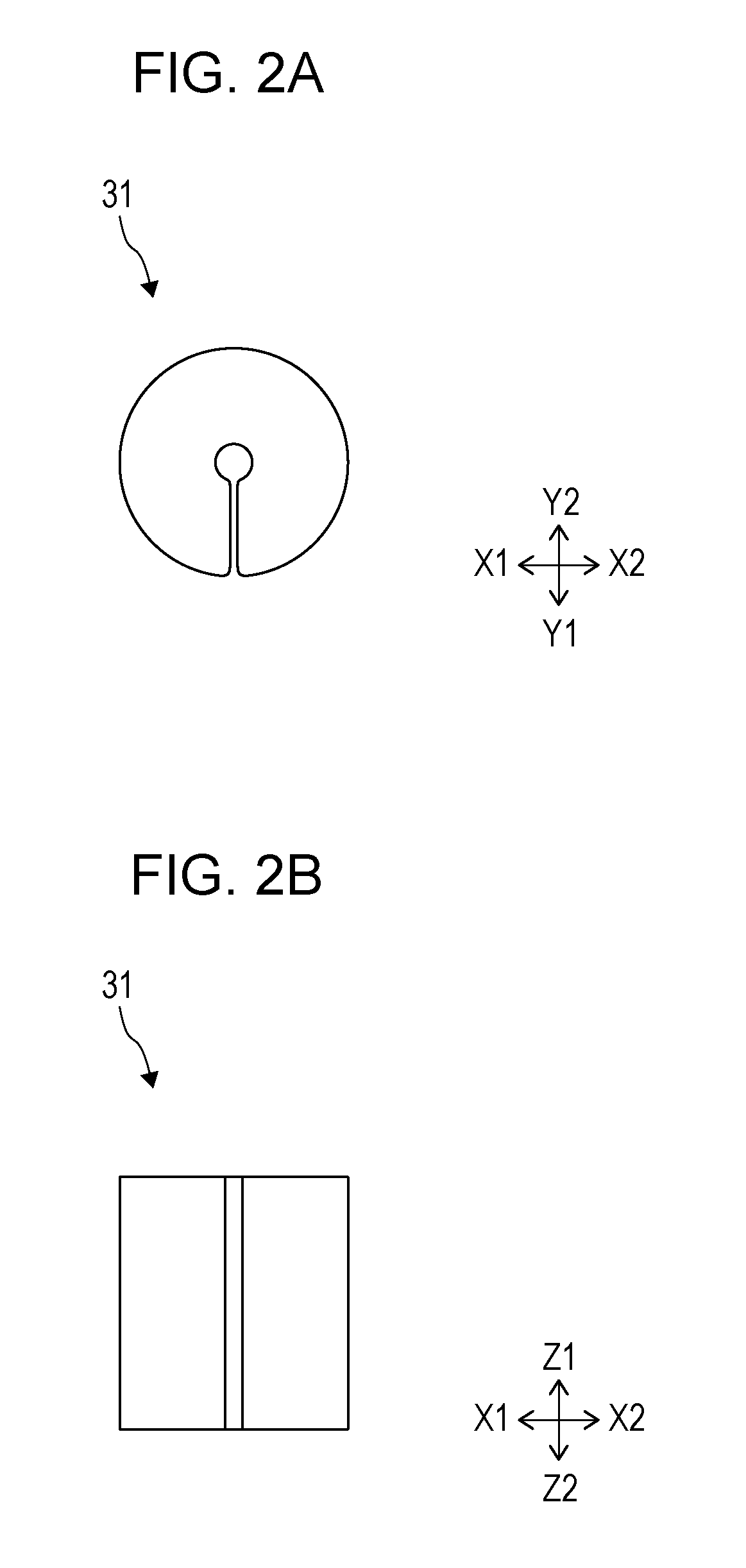
[0026]FIG. 1 is a sectional view of a temperature sensor 10 according to a first embodiment of the present invention. FIGS. 2A and 2B are external views of a heat insulating member 31; specifically, FIG. 2A is a plan view, and FIG. 2B is a front view. FIG. 3 is a sectional view illustrating a state in which a holder 16, the heat insulating member 31, and a substrate 17 are fixed to a wire member 14 that is connected to a temperature sensor element 11. FIG. 4 is a sectional view of a case 20 in a state before attaching a cap 23. FIG. 5 is a sectional view illustrating a state in which the temperature sensor element 11 is inserted into a tubular portion 22 of the case 20. FIG. 6 is a sectional view illustrating a state in which a retaining material 25 is filled.

[0027]The temperature sensor 10 according to the first embodiment of the present invention includes the temperature sensor element 11 accommodated in the case 20, and it is constituted as illustrated in the sectional view of FI...

second embodiment

[0046]FIG. 7 is a block diagram of a position detection device 100 according to a second embodiment of the present invention.

[0047]As illustrated in FIG. 7, the position detection device 100 according to this embodiment represents an example in which the position detection device 100 is attached to a throttle valve 220 for controlling an engine output. It is to be noted that the position detection device 100 can be used in various applications without being limited to such an example.

[0048]The position detection device 100 illustrated in FIG. 7 includes position detection means 2 configured to detect a position of a detection object, temperature sensing means 1 configured to sense an ambient temperature around the detection object, and pressure sensing means 3 configured to sense a pressure of taken-in gas (atmosphere). The temperature sensing means 1 includes the temperature sensor 10 according to the first embodiment.

[0049]The position detection means 2 detects the position of the...


PUM


Abstract

A temperature sensor includes a case including a body portion and a tubular portion projecting outward from the body portion, the tubular portion being formed in a tubular shape closed at a side defining a tip, a temperature sensor element arranged within the tubular portion at the tip, a wire member connected to the temperature sensor element, a retaining portion disposed within the tubular portion at a position closer to the body portion than the temperature sensor element, the retaining portion being filled with a retaining material to support the wire member, and a heat insulating section disposed between the temperature sensor element and the retaining portion, the heat insulating section including a heat insulating member made of a less heat-transferable material than the retaining material.

Description

CLAIM OF PRIORITY[0001]This application is a Continuation of International Application No. PCT / JP2016 / 079550 filed on Oct. 4, 2016, which claims benefit of Japanese Patent Application No. 2015-222110 filed on Nov. 12, 2015. The entire contents of each application noted above are hereby incorporated by reference.BACKGROUND OF THE INVENTION1. Field of the Invention[0002]The present invention relates to a temperature sensor for measuring a temperature of a fluid, such as air taken into an engine, and to a position detection device including the temperature sensor.2. Description of the Related Art[0003]Recently, temperature sensors have been used in various types of control in a vehicle. The temperature sensor includes a temperature sensor element coated with glass, for example, and has a structure that the temperature sensor element is arranged in a tip portion of a tip-closed tube for protection purposes. A tip of the temperature sensor element is held in direct contact with the tube ...

Claims


Application Information

Patent Timeline
IPC IPC(8): G01K1/12G01K7/24G01D5/12
CPCG01K1/12G01K7/24G01D5/12F02D2200/0406F02D2200/0414G01K1/08G01K7/22
Inventor SUGAWARA, TAIJISAITO, KYOZO
Owner ALPS ALPINE CO LTD
Why Eureka
Try Eureka