Dental Implants with Markers for Determining Three-Dimensional Positioning

Active Publication Date: 2018-08-16
ESTHETIC IMPLANT SOLUTIONS LLC
View PDF4 Cites 15 Cited by
  • Summary
  • Abstract
  • Description
  • Claims
  • Application Information

AI Technical Summary

Benefits of technology

[0005]Identifying the exact spatial position and orientation of the implant as installed in the jaw bone of a patient through imaging, including the relationship between the surrounding soft and hard oral tissues, would allow for more efficient fabrication of temporary and permanent prosthetics and attachments by limiting the amount of time and materials needed by the practitioner and laboratory. Such information would also minimize the multiplication of procedures to the patient. For example, at present, a patient typically is required to visit the practitioner multiple times as various iterations of the prosthetic are developed and fitted to the implant insta

Problems solved by technology

Because of limitations in the field of three-dimensional imaging, as well problems specific to its implementation with an installed dental implant, it has not yet been possible to provide sufficient three-dimensional image scanned data to identify the exact spatial position o

Method used


Image

  • Dental Implants with Markers for Determining Three-Dimensional Positioning
  • Dental Implants with Markers for Determining Three-Dimensional Positioning
  • Dental Implants with Markers for Determining Three-Dimensional Positioning

Examples


Embodiment Construction

I. Introduction

[0068]One problem with conventional healing caps and related methods of oral surgery is that those features of the gingiva that provide much of the characteristic natural aesthetic appearance of natural teeth and adjacent gum tissue are almost always lost once a tooth is pulled and replaced with a prosthesis. In particular, the gingival tissue surrounding the crown of a natural tooth where it emerges (i.e., its emergence profile) is lost during such procedures.

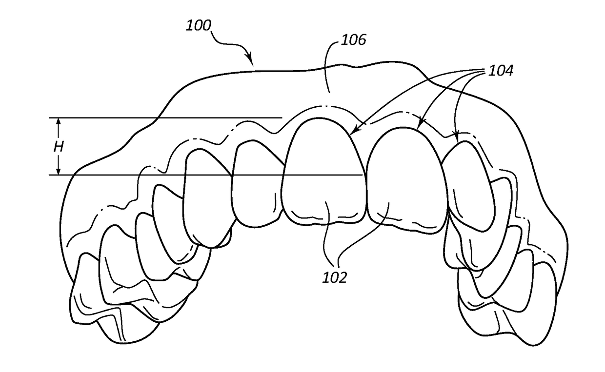
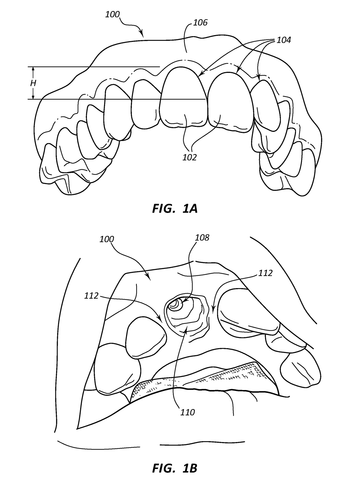
[0069]The gingival cuff refers to the generally scalloped pattern of the gingival tissue that is most prominently seen along the buccal surface of the teeth. The height of contour of the gingival cuff refers to the difference between the most occlusal extension of the gingiva (i.e., between teeth) as compared to its location at the center of a tooth. Generally, the height of contour of the gingival cuff is greatest at a location between two adjacent teeth. In other words, the location of the gingival cuff extend...


PUM


Abstract

Dental implants including radiopaque markers provided therein or thereon. The implant may also include customizable length characteristics. For example, a kit may include implants with different diameters (e.g., 3 diameters), where all of the implants are of a single (e.g., long) length. The appropriate diameter implant may be selected from the kit by the practitioner, and the long length implant may be cut (e.g., with a dental drill) to the appropriate length needed. The implants include radiopaque markers on or within the implant. For example, three series of markers may be provided on different “faces” of the implant, so that the three series of markers serve as reference points when scanning, allowing triangulation of the exact position of the implant in relation to the surrounding hard and soft oral tissues.

Description

CROSS-REFERENCE TO RELATED APPLICATIONS[0001]The present application is continuation-in-part of U.S. patent application Ser. No. 15 / 270,804 filed Sep. 20, 2016, which is a continuation-in-part of U.S. patent application Ser. No. 14 / 327,869 filed Jul. 10, 2014, now U.S. Pat. No. 9,895,209, which is a continuation-in-part of U.S. patent application Ser. No. 14 / 152,369, filed Jan. 10, 2014, now U.S. Pat. No. 9,572,640, which is a continuation-in-part of U.S. patent application Ser. No. 13 / 633,387 filed Oct. 2, 2012, now U.S. Pat. No. 8,628,327. U.S. patent application Ser. No. 14 / 327,869 is also a continuation in part of International Application No. PCT / US2013 / 020992, filed Jan. 10, 2013, which claims priority to U.S. patent application Ser. No. 13 / 347,127, filed Jan. 10, 2012, now abandoned. U.S. patent application Ser. No. 15 / 270,804 filed Sep. 20, 2016 is also a continuation-in-part of U.S. patent application Ser. No. 14 / 485,351, filed Sep. 12, 2014. The disclosure of each of the a...

Claims


Application Information

Patent Timeline
IPC IPC(8): A61C8/00A61C1/08
CPCA61C8/0093A61C1/084A61C8/0001A61C13/34A61C8/008A61C5/70A61C13/0004A61C9/0053A61C13/20A61C5/77A61C13/0001A61B2090/0808A61B2090/0811A61B2090/3937A61B2090/3966
Inventor LISTON, TODD C.BLAISDELL, MARK H.
Owner ESTHETIC IMPLANT SOLUTIONS LLC
Why Eureka
Try Eureka