
Compressor

a compressor and compression tube technology, applied in the field of compressors, can solve problems such as reliability problems and pipe bending, and achieve the effects of reducing the pulsation of refrigerant, reducing the cost, and reducing the vibration of pipes

Active Publication Date: 2018-08-23
DAIKIN IND LTD
View PDF7 Cites 0 Cited by
  • Summary
  • Abstract
  • Description
  • Claims
  • Application Information

AI Technical Summary

Benefits of technology

This patent relates to an improved compressor design that reduces pulsation and noise during operation. The compressor includes a pulsation attenuation space that communicates with either the injection passage or the expansion chamber, and the design also includes an expansion chamber that reduces pulsation of the refrigerant as it flows through the compressor. These features eliminate the need for a muffler or other expensive and bulky components, resulting in a more compact and cost-effective design. Additionally, the design ensures that the frequency of pulsation does not match the natural frequency of any components in the compressor, further reducing noise and vibration. Overall, the patent provides technical improvements that enhance the efficiency and performance of compressors.

Problems solved by technology

In the case of performing intermediate injection, vibration of pipes in the outdoor unit and radiating sound are produced by pulsation during injection, and when the vibration is large, there is also the potential for this to lead to pipe bending, which is a problem in terms of reliability.

Method used


Image

  • Compressor
  • Compressor
  • Compressor

Examples


first example modification

(7-1) First Example Modification

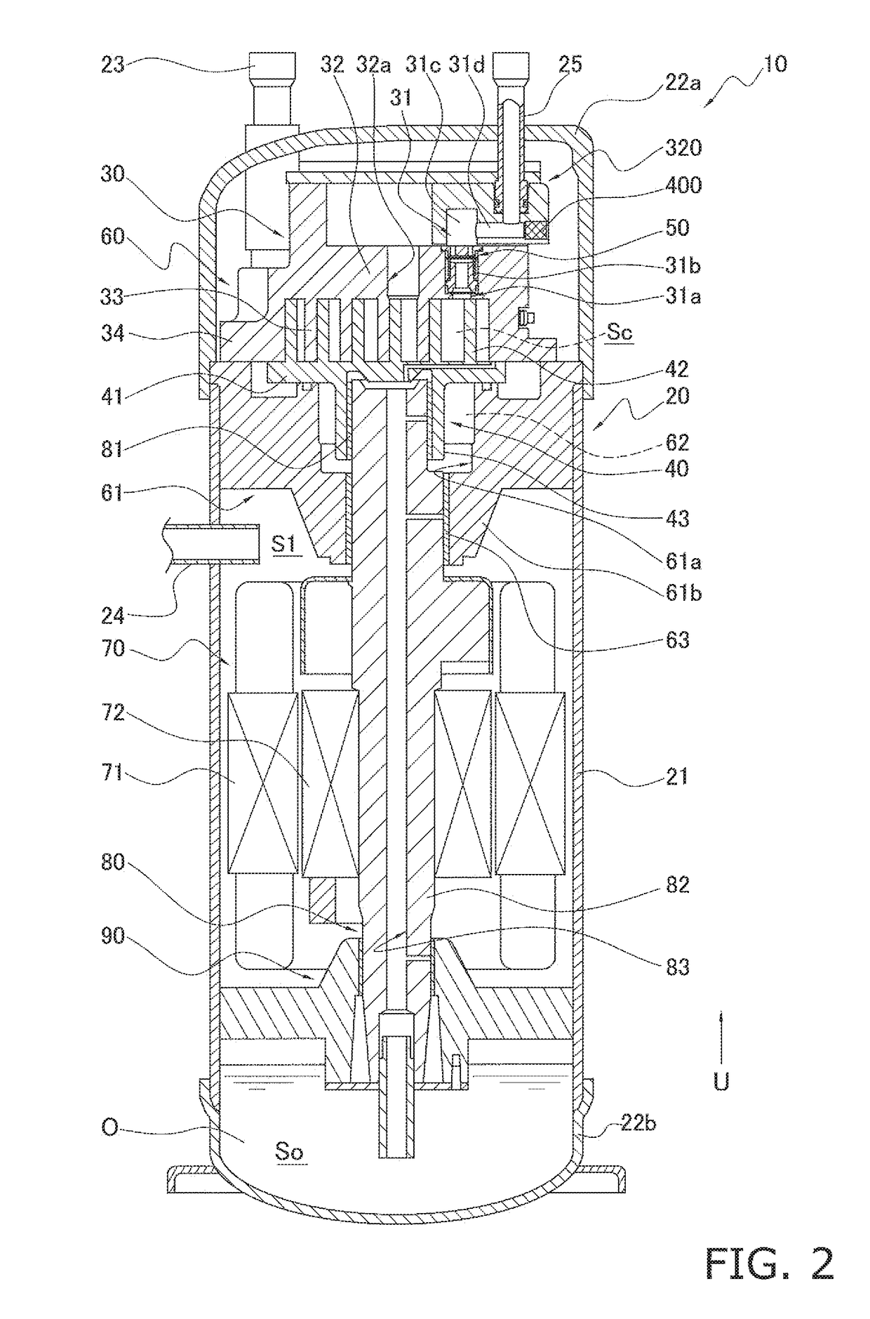
[0115]FIG. 5 is an enlarged view of the area around the injection passage in a first example modification. The scroll compressor 10 pertaining to the first example modification in FIG. 5 differs from the one in the above embodiment shown in FIG. 2 and FIG. 3 in that, instead of the expansion chamber 31c, a Helmholtz resonator 330 is disposed adjacent to the horizontal passage portion 31d. Consequently, configurations other than the resonator 330 are substantially the same as those in the above embodiment, so here just the resonator 330 and the section around the resonator 330 will be described.

[0116]In the first example modification, the Helmholtz resonator 330 is connected to the injection passage 31 leading from the injection pipe 25 to the compression chamber Sc. Specifically, the resonator 330 is connected so as to be adjacent to a branching region for branching from the horizontal passage portion 31d to the valve chamber 31b.

[0117]As shown in FI...

second example modification

(7-2) Second Example Modification

[0122]FIG. 6 is an enlarged view of the area around the injection passage in a second example modification. The scroll compressor 10 pertaining to the second example modification in FIG. 6 differs from the one in the above embodiment shown in FIG. 2 and FIG. 3 in that, instead of the expansion chamber 31c, a side branch resonator 340 is disposed adjacent to the horizontal passage portion 31d. Consequently, configurations other than the side branch resonator 340 are substantially the same as those in the above embodiment, so here just the side branch resonator 340 and the section around the side branch resonator 340 will be described.

[0123]In the second example modification, the side branch resonator 340 branches from and is connected to the injection passage 31 leading from the injection pipe 25 to the compression chamber Sc. Specifically, the resonator 340 is connected so as to branch from the horizontal passage portion 31d on the opposite side of t...


PUM


Abstract

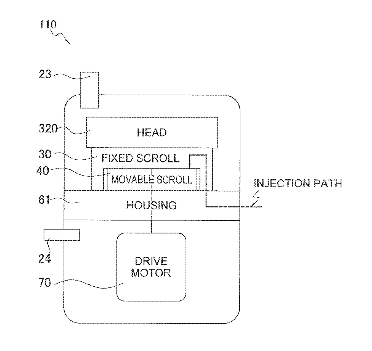
A compressor includes a compression chamber forming member, an injection passage, an injection pipe, and a pulsation attenuation space. The compression chamber forming member forms a compression chamber. The injection passage is formed in at least one of the compression chamber forming member and a separate member disposed in a surrounding area and connecting to the compression chamber. The injection pipe supplies refrigerant to the injection passage. The pulsation attenuation space is formed in one of the compression chamber forming member and the separate member disposed in the surrounding area so as to communicate with the injection passage. The pulsation attenuation space attenuates pulsation of refrigerant gas flowing from the injection pipe into the compression chamber.

Description

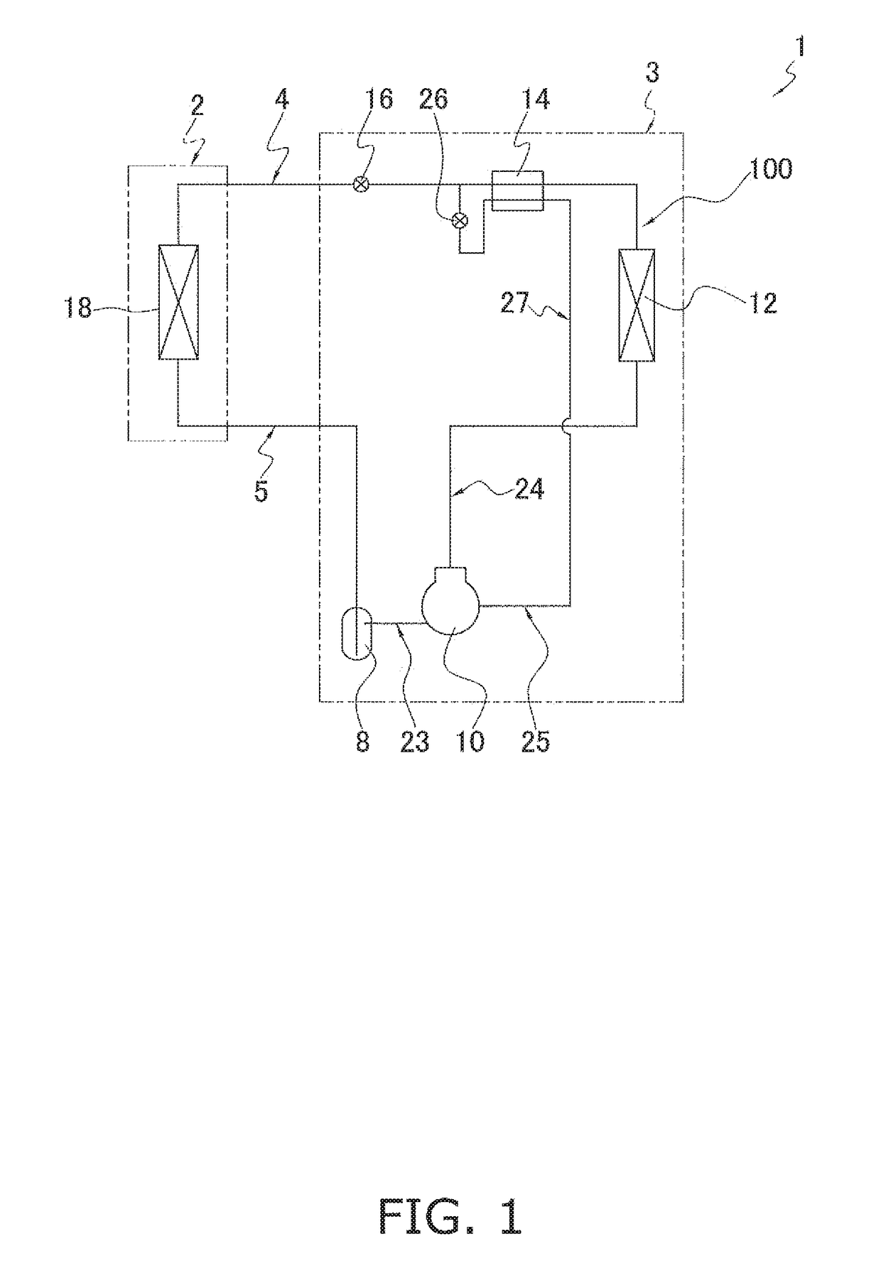
TECHNICAL FIELD[0001]The present invention relates to a compressor, and relates particularly to a compressor in which intermediate injection is performed.BACKGROUND ART[0002]Conventionally, there have been cases where intermediate injection is performed for the purpose of improving the efficiency of a compressor used in a refrigeration system, and there have been cases where an injection passage is formed in, for example, a fixed scroll member of the compressor in order to guide refrigerant injected into a compression chamber of the compressor. In the intermediate injection, refrigerant at a pressure (intermediate pressure) between a low pressure in the refrigeration cycle and a high pressure in the refrigeration cycle is injected into the compression chamber.[0003]In the case of performing intermediate injection, vibration of pipes in the outdoor unit and radiating sound are produced by pulsation during injection, and when the vibration is large, there is also the potential for thi...

Claims


Application Information

Patent Timeline
Patent Type & Authority Applications(United States)
IPC IPC(8): F04C29/06F04C18/02
CPCF04C29/065F04C18/0215F04C23/02F04C29/06F04C29/061F04C29/12F04C29/124F04C23/008F04C27/008F04C29/068F04C2240/806
Inventor TSUKA, YOSHITOMO
Owner DAIKIN IND LTD
Learn More