Automatic clutch device

a technology of automatic clutch and release cylinder, which is applied in the direction of clutches, non-mechanical actuated clutches, gearings, etc., can solve the problems of deteriorating the responsiveness of the clutch release cylinder, large installation space for such clutch devices, and large size of clutch devices, so as to achieve convenient disengagement and disengagement of automatic clutch devices. , the effect of compact siz

Active Publication Date: 2018-08-23
NTN CORP
View PDF0 Cites 5 Cited by
  • Summary
  • Abstract
  • Description
  • Claims
  • Application Information

AI Technical Summary

Benefits of technology

[0026]According to the present invention, as described above, since the rotation of the electric motor is converted to a linear motion of the release bearing by a rotation-linear motion conversion mechanism comprising at least two cam plates arranged in tandem with each other on the input shaft, and a torque cam mechanism, thereby pressing the pressure plate, compared to a conventional automatic clutch device in which the release fork is pivoted by the clutch release cylinder to move the release bearing toward the pressure plate, the automatic clutch device according to the present invention is compact in size, and does not require a large installation space.
[0027]Since the electric motor as the driving source is activated and deactivated by operating a switch, and its operation is not influenced by changes in the surrounding environment such as a change in temperature, the automatic clutch device according to the present invention is sufficiently responsive.
[0028]The reverse input blocking mechanism, which is provided in the torque transmission path from the electric motor to the output-side cam plate for pressing the release bearing, makes it possible to reliably keep the automatic clutch device disengaged.

Problems solved by technology

Since the clutch device of either of Patent Documents 1 and 2 is configured to be engaged and disengaged by pivoting the release fork with the clutch release cylinder, such clutch devices tend to be large in size.
Moreover, since such clutch devices require a hydraulic pump, and pipe connections between the hydraulic pump and the clutch release cylinder, a large installation space is needed for such clutch devices.
While the ambient temperature is low, hydraulic pressure used to activate the clutch release cylinder flows less smoothly in the pipes due to elevated viscosity of the hydraulic oil, thus deteriorating responsiveness of the clutch release cylinder.

Method used


Image

  • Automatic clutch device
  • Automatic clutch device
  • Automatic clutch device

Examples


Embodiment Construction

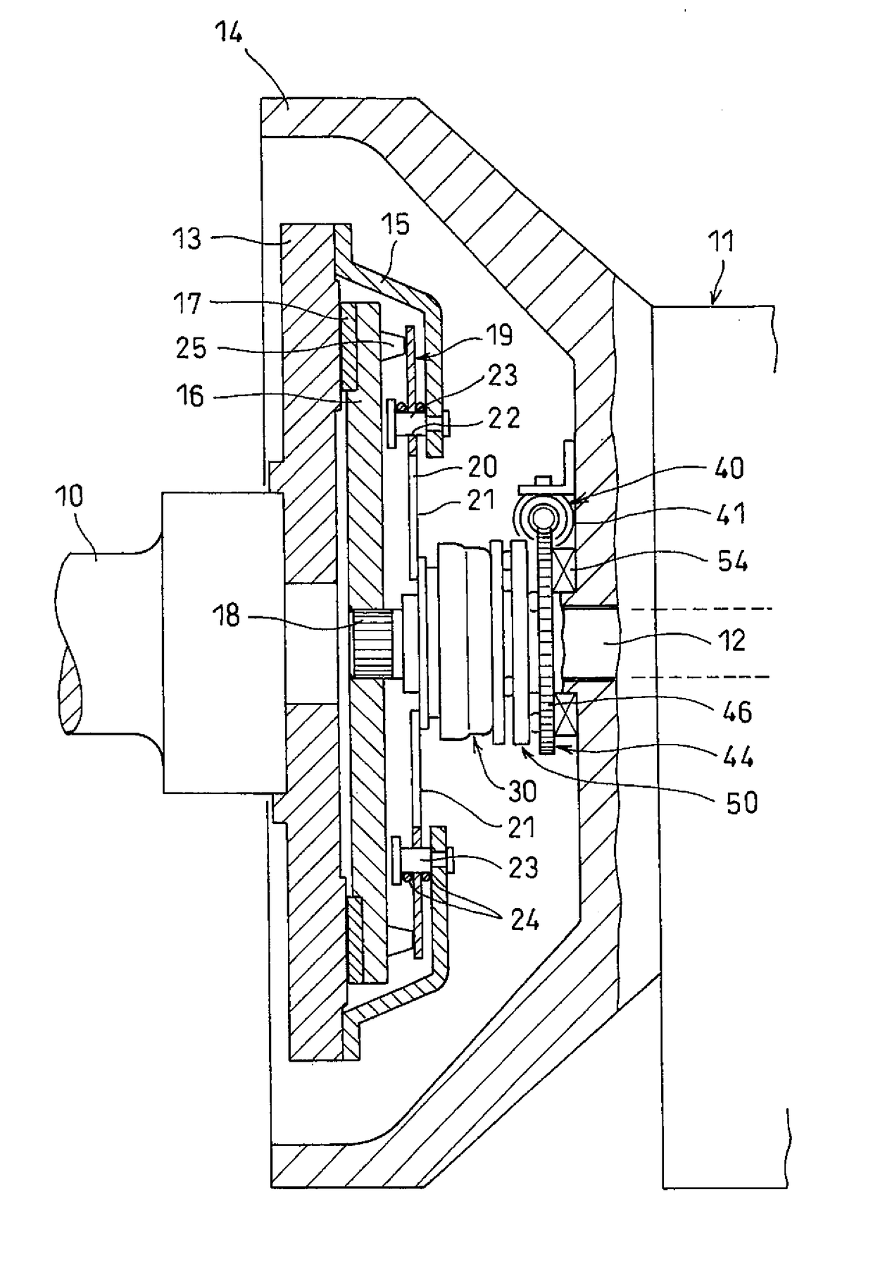
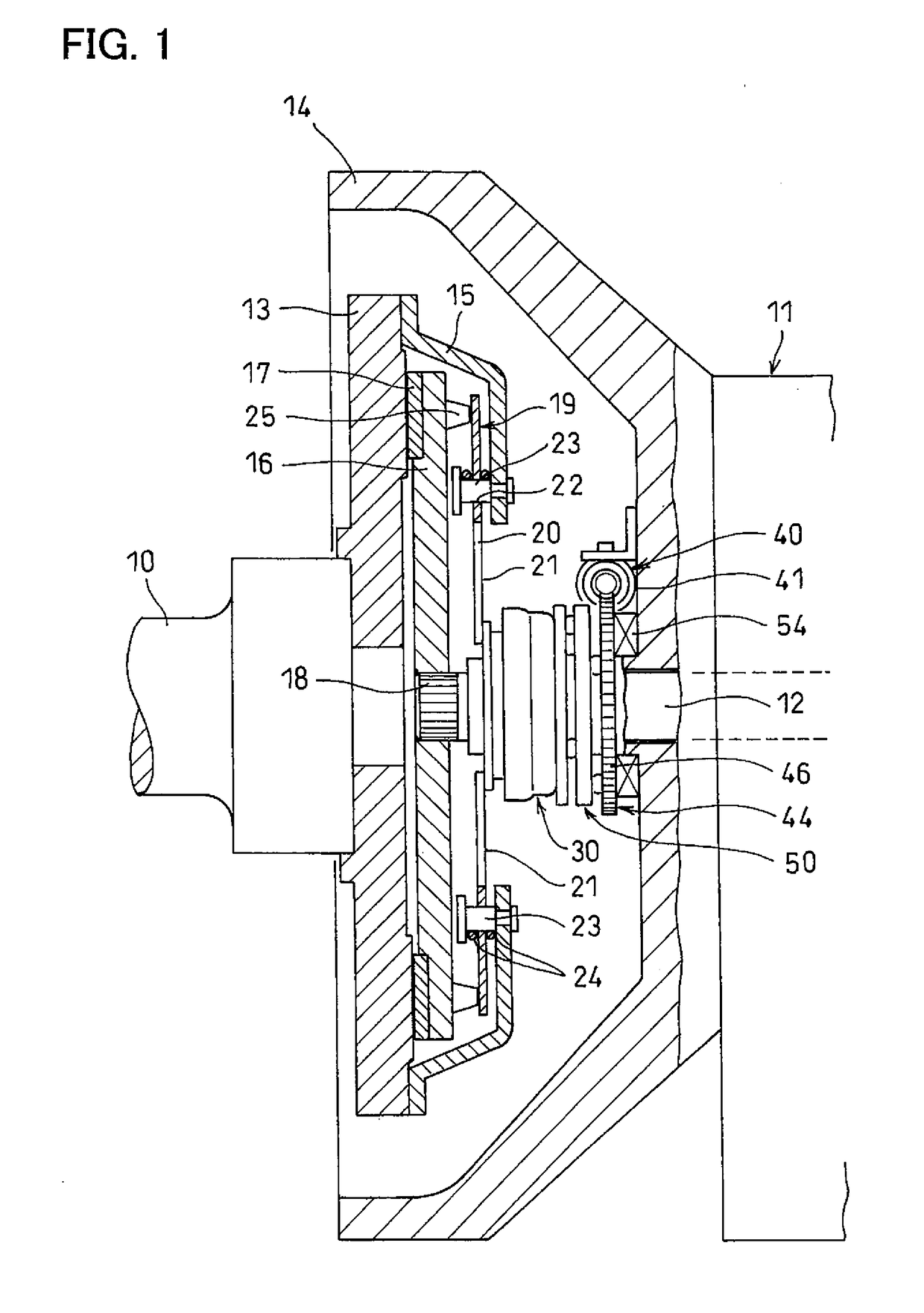
[0045]Embodiments of the present invention are now described with reference to the drawings. FIG. 1 shows an input shaft 12 of a transmission 11 including gears mounted on parallel shafts, the input shaft 12 being arranged coaxial with a crankshaft 10 of an engine.

[0046]A flywheel 13 is fixed to the end of the crankshaft 10 opposed to the input shaft 12, and is located inside of, so as to be rotatable relative to, a clutch housing 14 of the transmission 11.

[0047]A clutch cover 15 is mounted to the outer peripheral portion of the outer side surface of the flywheel 13 that is opposed to the transmission 11. A clutch disk 16 is mounted in the clutch cover 15.

[0048]A facing 17 is fixed to the outer peripheral portion of the outer side surface of the clutch disk 16 that is opposed to the flywheel 13. The clutch disk 16 is fitted to serrations 18 formed on the outer periphery of the end of the input shaft 12 so as to be rotationally fixed and axially slidable, relative to the input shaft ...


PUM


Abstract

An automatic clutch device includes an axial force generating mechanism including an electric motor arranged adjacent to the outer periphery of an end of an input shaft of a transmission, and a rotation-linear motion conversion mechanism for converting the rotation of the rotor of the electric motor to a linear motion of a release bearing. The rotation-linear motion conversion mechanism includes plural annular cam plates arranged in tandem on the input shaft, and torque cam mechanisms each disposed between each opposed pair of cam plates, for reduced size and improved responsiveness of the automatic clutch device.

Description

TECHNICAL FIELD[0001]The present invention relates to an automatic clutch device for selectively transmitting and not transmitting the power from an engine crankshaft to the input shaft of the transmission.BACKGROUND ART[0002]The below-identified Patent Documents 1 and 2 disclose known automatic clutch devices for automatically engaging and disengaging manual transmissions (MT) and automated manual transmissions (AMT).[0003]The automatic clutch device disclosed in Patent Document 1 is configured such that when the clutch pedal is depressed, hydraulic pressure is generated in a master cylinder mechanically connected to the clutch pedal, and is supplied to a clutch release cylinder, the clutch release cylinder pivots a release fork, thereby pressing a release bearing, a pressure plate is pressed against a flywheel under the pressing force applied to the pressure plate from the release bearing, and the clutch device engages.[0004]The automatic clutch device disclosed in Patent Document...

Claims


Application Information

Patent Timeline
Patent Type & Authority Applications(United States)
IPC IPC(8): F16D23/12F16D28/00F16D13/40F16H25/12
CPCF16D23/12F16D28/00F16D13/40F16H25/125F16D2023/123F16H1/16F16D23/14F16D2013/565
Inventor SAITO, TAKAHIDESATOKAWAI, MASAHIROIKEDA, ATSUSHI
Owner NTN CORP
Why Eureka
Try Eureka