
Smart-security digital system, method and program

a digital system and security technology, applied in the field of smart security digital system, method and program, can solve the problems of insufficient rushing, difficult rushing from security guards room and office room,

Active Publication Date: 2018-08-23
TECHNOMIRAI
View PDF3 Cites 14 Cited by
  • Summary
  • Abstract
  • Description
  • Claims
  • Application Information

AI Technical Summary

Benefits of technology

The present invention allows for quick identification and response to individuals with habitual shoplifting or suspicious behavior. This prevents damage or loss to the company and ensures safety for employees.

Problems solved by technology

However, in these conventional shoplifting prevention systems, as a method of notifying an employee near a habitual shoplifter, an alarm, an interphone, or a wireless mobile device is used, however, in a case where an employee cannot know who is near him / her, an employee near the shoplifter is not aware of the notification due to noise or the like of a sales floor, or cannot respond to the notification because of stocking shelves or physiological reasons, a security guard must rush by the notification, however, in this case, such a rushing is insufficient since the habitual shoplifter may have already completed an act of shoplifting, moved to another sales floor, or left the store.
In particular, in large-scaled malls and home centers, etc., rushing from a security guards room and an office room, etc., is difficult.

Method used


Image

  • Smart-security digital system, method and program
  • Smart-security digital system, method and program
  • Smart-security digital system, method and program

Examples


embodiment

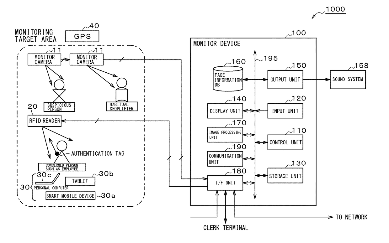
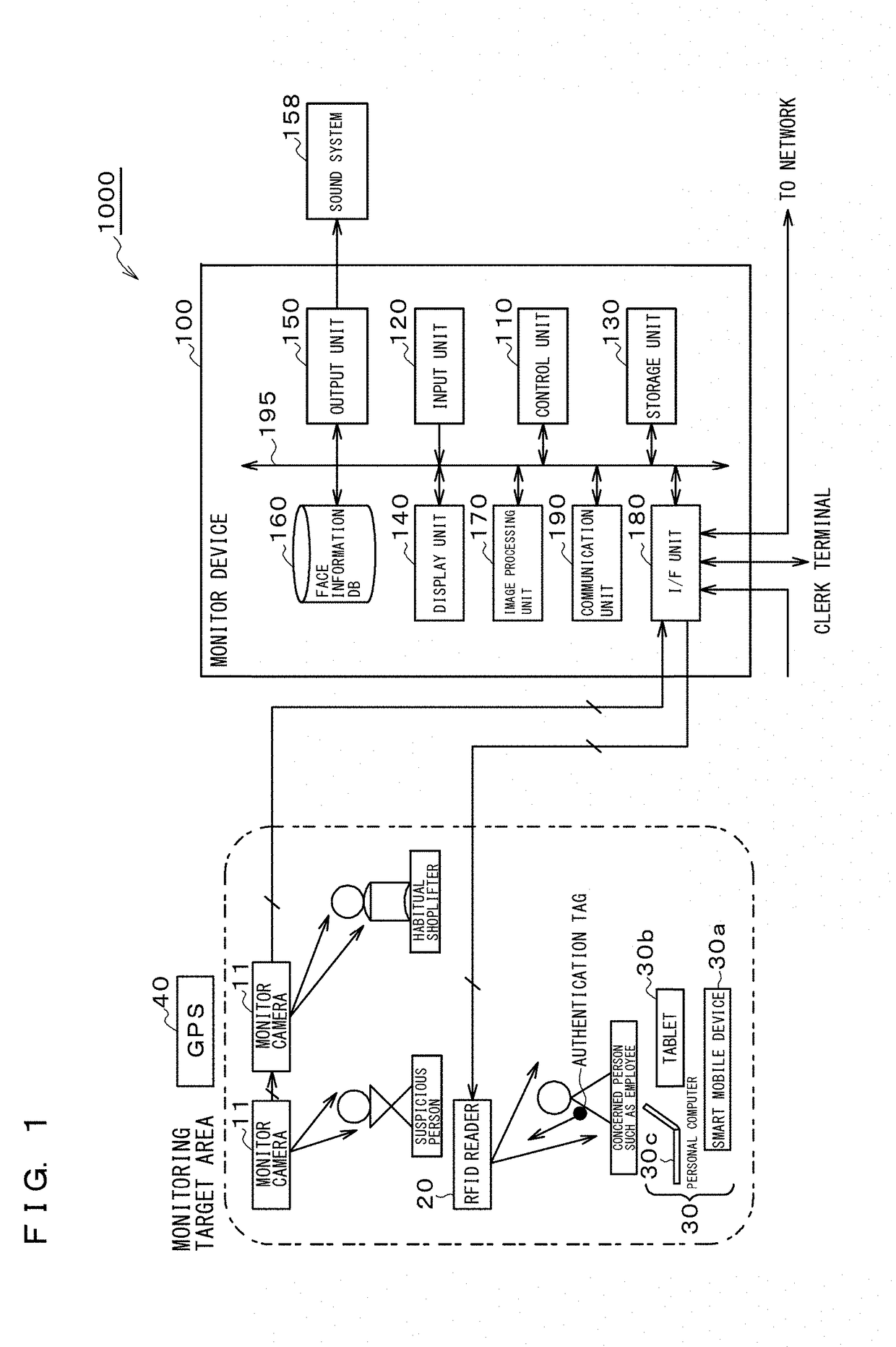
[0036]FIG. 1 is a block diagram showing a configuration of a smart-security digital system according to an embodiment of the present invention.

[0037]As shown in FIG. 1, a smart-security digital system 1000 comprises a plurality of monitor cameras 11 installed on a ceiling, etc., of a monitoring target area, RFID (Radio Frequency IDentification) readers 20 installed on store shelves, etc., in the monitoring target area, authentication tags 21 that concerned persons such as employees (hereinafter, referred to as employees) carry with them and are authenticated by the RFID readers 20, a GPS (Global Positioning System) 40 that captures positions of employees in the monitoring target area, and a monitor device 100 that controls the whole system.

[0038]The smart-security digital system 1000 monitors videos from the monitor cameras 11 installed in the monitoring target area and notifies the mobile terminal device 30 that an employee carries with him / her information on a habitual shoplifter ...

application example 1

[0154]Description will now be given, in the case of sales floors of a commercial facility, of a sales floor configuration of the smart-security digital system 1000.

[0155]FIG. 10A and FIG. 10B are views showing an example of a sales floor layout of the smart-security digital system.

[0156]In the smart-security digital system 1000, the monitor device 100 stores sales floor layout positional information, positional information of the RFID readers 20 on the sales floor layout 200, and employees' positional information acquired by the RFID readers 20.

[0157]In the sales floor corners, the monitor cameras 11 and the RFID readers 20 are respectively installed. If GPS radio waves are unstable and the radio waves do not reach, positional information can be acquired by the RFID reader 20.

[0158]The monitor device 100, if having recognized a habitual shoplifter or suspicious behavior person by the monitor camera 11, displays on a sales floor layout of the display unit 140 where the habitual shopl...

application example 2

[0169]FIGS. 11A and 11B include views showing an example of a sales floor layout of the smart-security digital system. FIG. 11A is a first-floor sales floor planar layout with a GPS and an arrangement plan of monitor cameras 11, and FIG. 11B is a first-floor sales floor planar layout by “X marks” of RFID readers and an arrangement plan of monitor cameras. In addition, other floors also have almost the same sales floor layout.

[0170]

[0171]As shown in FIG. 11A, it is assumed that a habitual shoplifter X has come to the store from the 1st-floor east entrance / exit.

[0172]The monitor device 100 focuses on and tracks the habitual shoplifter X “● (filled circle)” by the monitor cameras 11.

[0173]The monitor device 100 transmits information on the habitual shoplifter X (refer to FIG. 7A) to the mobile terminal device 30 (smartphone 30a, tablet 30b, or notebook PC 30c) that the 1st-floor employee A “⊚ (double circle)” present at the closest position carries with him / her. Here, the information o...


PUM


Abstract

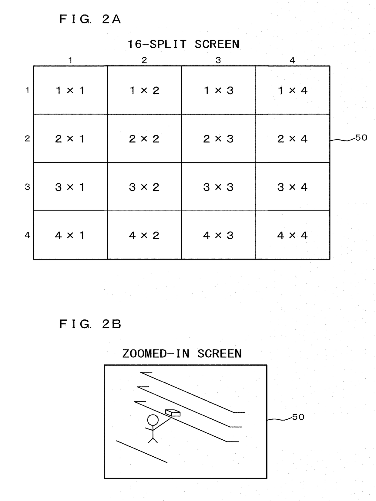
Provided is a smart-security digital system that enables, when there is a habitual shoplifter or suspicious behavior person, an employee or the like close to the habitual shoplifter or suspicious behavior person to quickly rush to the scene and prevent an act of shoplifting. The smart-security digital system (1000) comprises a face authentication function unit (111) that collates with facial images of habitual shoplifters or suspicious behavior persons accumulated in a face information DB (160), a control unit (110) that determines, when a result of collation by the face authentication function unit (111) is a match, a position of a mobile terminal device (30) closest to the habitual shoplifter or suspicious behavior person the collation result with whom is a match based on positional information acquired from a position determination unit (113), and transmits information on the habitual shoplifter or suspicious behavior person to the mobile terminal device (30), and an image processing unit (170) that synthesizes videos shot by monitor cameras (11) into a display screen consisting of a plurality of split screens, and performs a zoom-in processing to zoom in one of the split screens.

Description

TECHNICAL FIELD[0001]The present invention relates to a smart-security digital system, method and program to prevent shoplifting of a habitual shoplifter or the like by monitoring videos shot by monitor cameras.BACKGROUND ART[0002]The retail industry has spent huge amounts of money on measures against shoplifting. Shoplifting causes not only a direct loss of profits but also, due to a shortage of supply and stockout, a loss of sales opportunity leading to huge operating losses. As defense measures, patrol and surveillance by security guards, monitoring by security cameras, and monitoring by face authentication cameras, etc., are performed.[0003]Patent Literature 1 describes a shoplifting prevention system at a gate of which a monitor camera is provided and which acquires face information from a received image, refers to face information saved in a storage device, and displays a screen showing the position of shooting in the store if a person corresponding to the face information has...

Claims


Application Information

Patent Timeline
Patent Type & Authority Applications(United States)
IPC IPC(8): G06K9/00G08B13/196
CPCG06K9/00228G06K9/00771G08B13/19684G08B13/19689G08B25/04H04N7/181G06V20/52H04N7/18G06V40/161
Inventor MIWA
Owner TECHNOMIRAI
Learn More