Phase-error correction in a synthetic aperture imaging system with local oscillator time delay adjustment

a synthetic aperture imaging and time delay adjustment technology, applied in the field of synthetic aperture imaging, can solve the problems of preventing or hindering the ability to make real-time or near-real-time adjustment of the relative path length difference between, phase errors, and laser phase nois

Active Publication Date: 2018-08-23
INSTITUT NATIONAL D'OPTIQUE
View PDF1 Cites 23 Cited by
  • Summary
  • Abstract
  • Description
  • Claims
  • Application Information

AI Technical Summary

Problems solved by technology

A challenge in SAL imaging lies in the adjustment of the optical path length of the LO signal to match the round-trip path length of the transmitted / returned (main) signal, to ensure that the spectrum of the beat signal falls within the bandwidth of the detector.
A drawback of this approach is that different delay lines must be used for different target ranges, thus preventing or hindering the ability to make real-time or near real-time adjustment of the relative path length difference between the main and LO signals.
Another challenge in SAL imaging is the measurement and correction of phase errors.
As SAL imaging relies on coherent detection, it is susceptible to laser phase noise.
Laser phase noise arises from the finite coherence length and other instabilities of laser sources and causes phase errors that can degrade the image reconstruction process.
Furthermore, any uncompensated fluctuations in the relative path length difference, or relative temporal delay, between the main signal and the LO signal can affect the phase of the measured signal and, in turn, lead to phase errors that impair the integrity of the measured signals.

Method used


Image

  • Phase-error correction in a synthetic aperture imaging system with local oscillator time delay adjustment
  • Phase-error correction in a synthetic aperture imaging system with local oscillator time delay adjustment
  • Phase-error correction in a synthetic aperture imaging system with local oscillator time delay adjustment

Examples


Embodiment Construction

[0034]In the following description, similar features in the drawings have been given similar reference numerals, and, to not unduly encumber the figures, some elements may not be indicated on some figures if they were already identified in one or more preceding figures. It should also be understood herein that the elements of the drawings are not necessarily depicted to scale, since emphasis is placed upon clearly illustrating the elements and structures of the present embodiments.

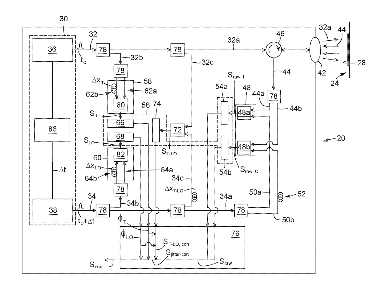
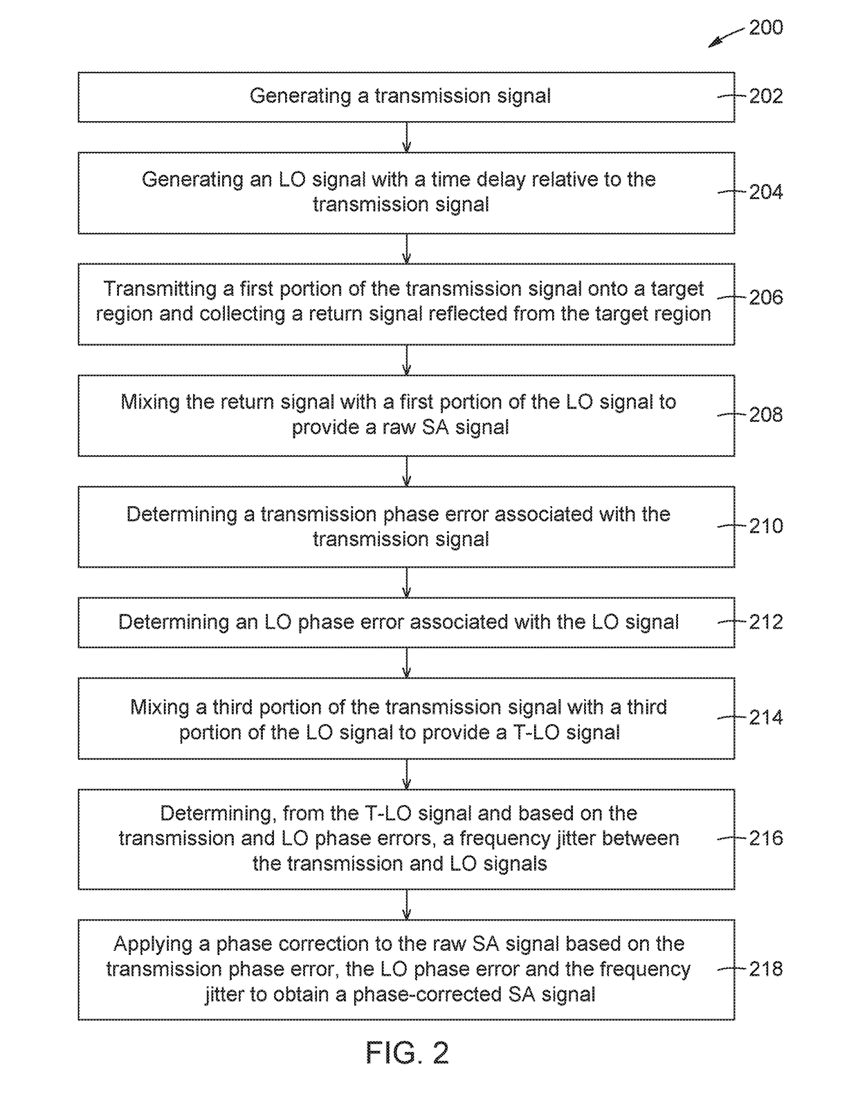
[0035]The present description generally relates to a method for phase-error correction in a synthetic aperture (SA) imaging system with temporal delay adjustment of the local oscillator (LO) signal. The present description also generally relates to an SA imaging system capable of implementing the method.

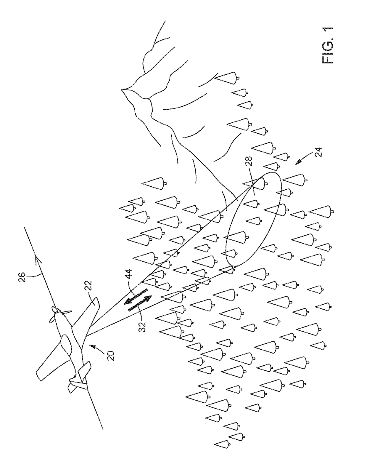
[0036]Referring to FIG. 1, there is provided a schematic representation of a conventional SA imaging system 20 mounted on a moving platform 22 flying over a scene 24, for example a ground surface of the Ear...


PUM


Abstract

A method is for phase-error correction in a synthetic aperture (SA) imaging system. A transmission signal and a local oscillator (LO) signal are generated with a relative time delay, which can be adjusted in real-time to match a range to a target region to be imaged. A portion of the transmission signal is transmitted onto the target region and a return signal is collected and mixed with a portion of the LO signal to provide a raw SA signal. Transmission and LO phase errors associated respectively with the transmission and LO signals are determined, as well as a frequency jitter between the transmission and LO signals. A phase-corrected SA signal is obtained by applying a phase correction to the raw SA signal based on the transmission phase error, the LO phase error and the frequency jitter. An SA imaging system is capable of implementing the method for phase-error correction.

Description

TECHNICAL FIELD[0001]The technical field generally relates to synthetic aperture (SA) imaging, and more particularly, to techniques for phase-error correction in a synthetic aperture imaging system with local oscillator (LO) time delay adjustment.BACKGROUND[0002]SA imaging can be used to increase resolution beyond the diffraction limit of a physical aperture of an imaging system. In SA imaging systems, a large “virtual” aperture is synthesized along a path by coherently summing the amplitude and phase information of return echoes from a plurality of electromagnetic signals sequentially transmitted by a relatively small physical aperture provided on a platform moving along the path. SA imaging systems generally include a transmitter-receiver unit mounted on an airborne, spaceborne, or terrestrial platform traveling along a path over a target region to be imaged. The transmitter-receiver unit directs a plurality of electromagnetic signals onto the target region and collects a series o...

Claims


Application Information

Patent Timeline
Patent Type & Authority Applications(United States)
IPC IPC(8): H04B10/61H04L7/00H03D7/12G01S7/484G01S7/497G01S7/486G01S17/26G01S17/34G01S17/90
CPCH04B10/6165H04L7/0037G01S7/497G01S7/484H03D7/12G01S7/486G01S17/26G01S17/90G01S17/34
Inventor TURBIDE, SIMONBERGERON, ALAIN
Owner INSTITUT NATIONAL D'OPTIQUE
Why Eureka
Try Eureka