Patient Mobility Assessment Device

a patient mobility and assessment technology, applied in the field of patient mobility assessment devices, can solve the problems of not being easily or accidentally removed from the display, and achieve the effects of increasing the amount, intensity and/or frequency of ambulation, facilitating measurement or calculation of one or more patient mobility parameters, and increasing tim

Active Publication Date: 2018-08-30
FIREFLY MEDICAL
View PDF4 Cites 14 Cited by
  • Summary
  • Abstract
  • Description
  • Claims
  • Application Information

AI Technical Summary

Benefits of technology

[0018]The methods and devices provided herein facilitate measurement or calculation of one or more patient mobility parameters. Examples of patient mobility parameters of interest include distance traveled, total movement time, trip or ambulation frequency, travel speed, or a combination thereof. The patient mobility assessment device may be configured to receive and display a patient mobility protocol from a medical caregiver or provider based on a desired patient mobility parameter, which, in turn, may depend on patient recovery and ambulation. The patient mobility protocol may be total movement time, total movement distance, average speed range, ambulation frequency or a combination thereof. This protocol may vary with time post-procedure, such as for increasing time since a procedure, an increase in the amount, intensity and/or frequency of ambulation. In other words, the patient mobility parameter may be time-varying, reflecting a desired ambulation time and intensity that increases with time since the medical procedure. In this manner, a patient during ambulation phase with the dev

Problems solved by technology

The display may be reversibly or more permanently incorporated into the mobility device,

Method used


Image

  • Patient Mobility Assessment Device
  • Patient Mobility Assessment Device
  • Patient Mobility Assessment Device

Examples


example 1

Assistance Device with Caster Distance Tracker and Receiving Unit

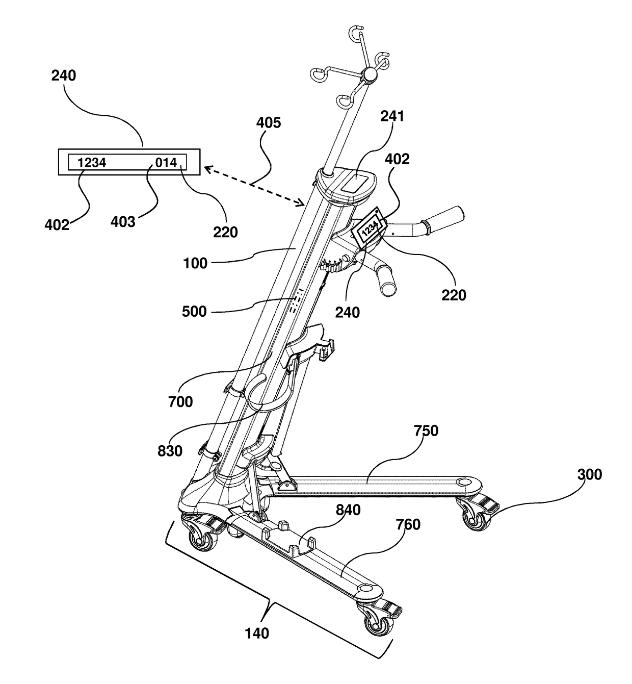
[0045]Referring to FIGS. 1-3 the mobility assistance device 100 may have a caster 300 and a display 220. Optionally the display 220 may be incorporated into a receiving unit 240 as shown in FIGS. 2A and 2B.

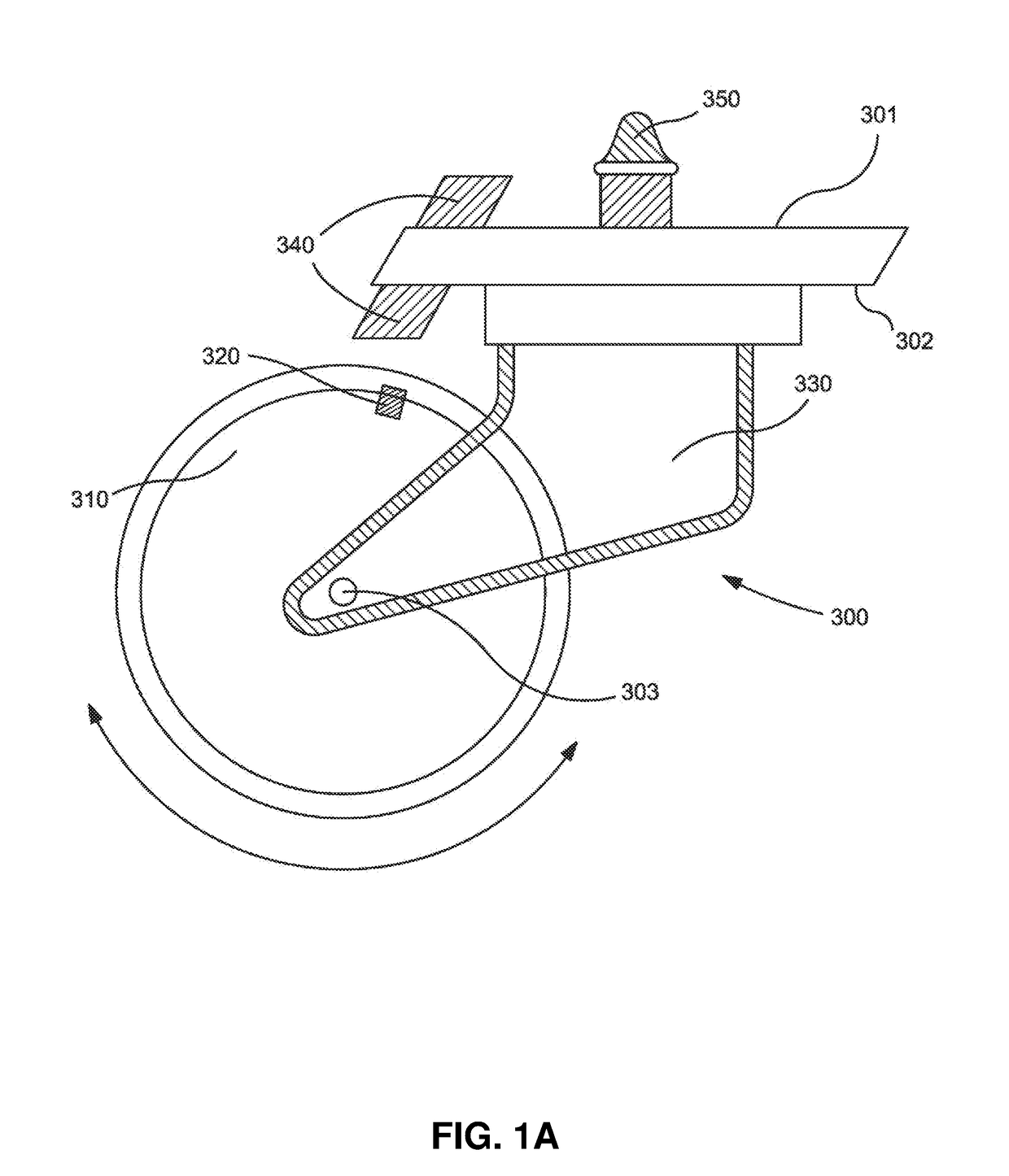
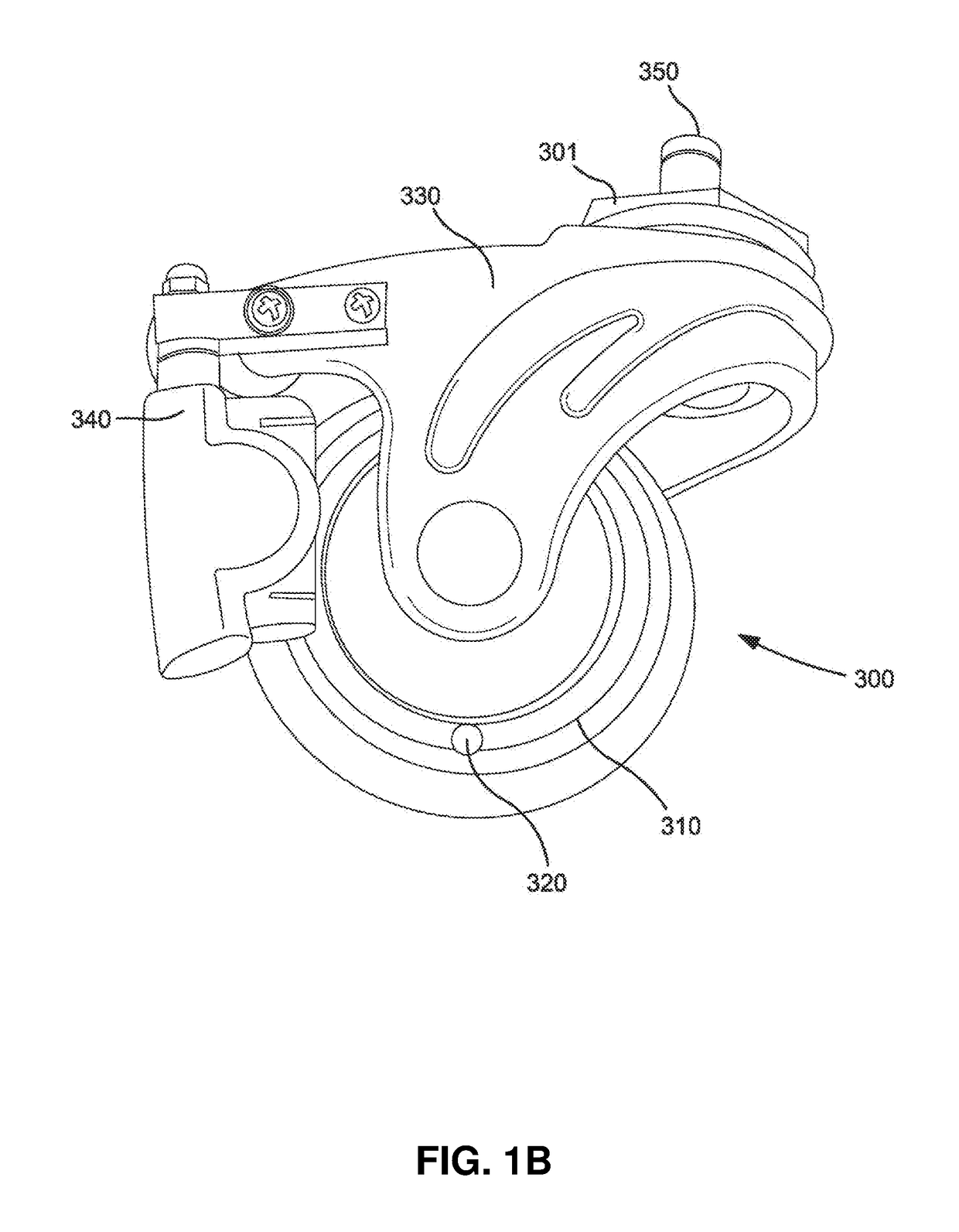
[0046]As illustrated in FIGS. 1A and 1B, the caster 300 has a wheel 310, a magnet 320, and a fork 330 that is connected to a sensor 340 having a relay. As the wheel 310 rotates in either direction (indicated by the double sided arrow), the magnet 320 passes the sensor 340, which relays a signal indicating distance traveled to a receiving unit 240 (FIGS. 2A and 2B) that may be connected via protrusion 230 to the mobility assistance device 100 via orifice 120. The caster 300 may also have a pin or protrusion 350 for attaching the caster to the mobility assistance device, such as by positioning with a correspondingly configured orifice positioned in the base. The fork may have a top fork surface 301, bottom fork surface...

example 2

d Systems

[0049]The tracking system illustrated in FIGS. 1A and 1B is one example of an accessory type feature that can be used to convert a mobility assistance device to a patient mobility assessment device, such as by incorporation of the wheel caster 300 with distance tracker. In other examples, the distance tracker may be a GPS-type location-based tracking device that can be positioned in other locations, besides the wheel. In other words, the distance tracker may be connected at other locations than at a wheel caster. For applications where it is desired that the tracking sensor device is discretely used, the sensor may be located in an interior portion 500 of the mobility assistance device, as illustrated by FIG. 4. Of course, any other convenient location may be used, including any interior-facing or exterior facing surface. One example of another possible location is identified as 241 on FIGS. 3A and 4, including a flush-mounted display. As illustrated in FIG. 4, a display 22...

example 3

obility Assessment

[0052]Referring to FIGS. 4 and 5, a receiving unit 240 may be used to functionally obtain information useful for patient mobility assessment. The receiving unit 240 may provide patient mobility parameters 402, such as total distance traveled, total steps, duration of travel, average speed, and / or longest continuous travel time. These parameters 402 may be monitored on a display 220 that is connected to the mobility assistance device (FIG. 4); or on a display 220 that is located at a remote location, such as at a remote work or nurses' station 610 (FIG. 5). A graphical user interface 221 may be provided on the display 220, via communication connection between the receiving unit 240 and workstation computer 240, as indicated by dashed arrow 223. This allows rapid and efficient evaluation of patient ambulation, even for multiple mobility assessment devices that are moving simultaneously. The receiving unit itself may correspond to a computer that is operably connected...


PUM


Abstract

Provided herein are patient mobility assessment devices having a mobility assistance device with an incorporated distance tracker for use in assessing the ambulation of a recovering medical patient. The distance tracker can be integrated into or removably attached to the mobility assistance device. The information obtained may be displayed on the mobility assistance device and/or at a nurse's station or other remote location for convenient monitoring of patient ambulation. Also provided herein are methods for evaluating patient ambulation using the mobility assessment device and optionally, provision of therapeutic ambulation protocols to a display on the device to assist with patient physical therapy and recovery.

Description

CROSS-REFERENCE TO RELATED APPLICATIONS[0001]This application claims the benefit of and priority to U.S. Provisional Patent Application No. 62 / 139,496 filed Mar. 27, 2015, which is hereby incorporated by reference to the extent not inconsistent herewith.BACKGROUND OF INVENTION[0002]Provided are ambulation devices and related methods that include distance tracking features for assessing the mobility of recovering medical patients. Early and safe ambulation is critical to patient recovery, and methods to encourage, measure and assess patient ambulation are an important aspect with respect to evolving healthcare protocols. A convenient means of measuring patient mobility, such as by the distance, speed, and regularity with which a patient is able to walk after having a medical procedure is desired.[0003]U.S. Pub. No. 2008 / 0221928 describes a system for monitoring the activity of a medical patient. That system employs a device worn by the patient that communicates with specially located...

Claims


Application Information

Patent Timeline
IPC IPC(8): A61B5/11A61B50/13A61M5/14A61B5/00A61H3/04G01C22/00G01S19/14G16H40/67G16H20/30
CPCA61H2201/5097A61H2203/0406A61B5/1113A61B50/13A61M5/1415A61B5/1112A61B5/7445A61B5/1118A61H3/04G01C22/00G01S19/14G16H40/67A61H2201/5043A61H2201/5064A45B3/00A45B2009/002A61B5/6894A61B5/1115A61B5/6812A61H2201/5007A61H2201/5012A61H2201/5048G16H20/30
Inventor SCHMUTZER, STEPHEN E.SCHOENIG, DARRELL
Owner FIREFLY MEDICAL
Why Eureka
Try Eureka