Misfire detection device for internal combustion engine

Active Publication Date: 2018-08-30
TOYOTA JIDOSHA KK
View PDF0 Cites 8 Cited by
  • Summary
  • Abstract
  • Description
  • Claims
  • Application Information

AI Technical Summary

Benefits of technology

[0020]According to the aspect of the present disclosure, the degree to which the rotation change value at the time of misfire is affected by a value other than misfire is lower than when the difference between a rotation time period needed for rotation corresponding to the rotation angle interval of one of the cylinders successive in time series

Problems solved by technology

Thus, a decrease in the rotation speed of the crankshaft at the presence of misfi

Method used


Image

  • Misfire detection device for internal combustion engine
  • Misfire detection device for internal combustion engine
  • Misfire detection device for internal combustion engine

Examples


embodiment

[0029]Hereinafter, one embodiment of a misfire detection device for an internal combustion engine will be described with reference to the drawings.

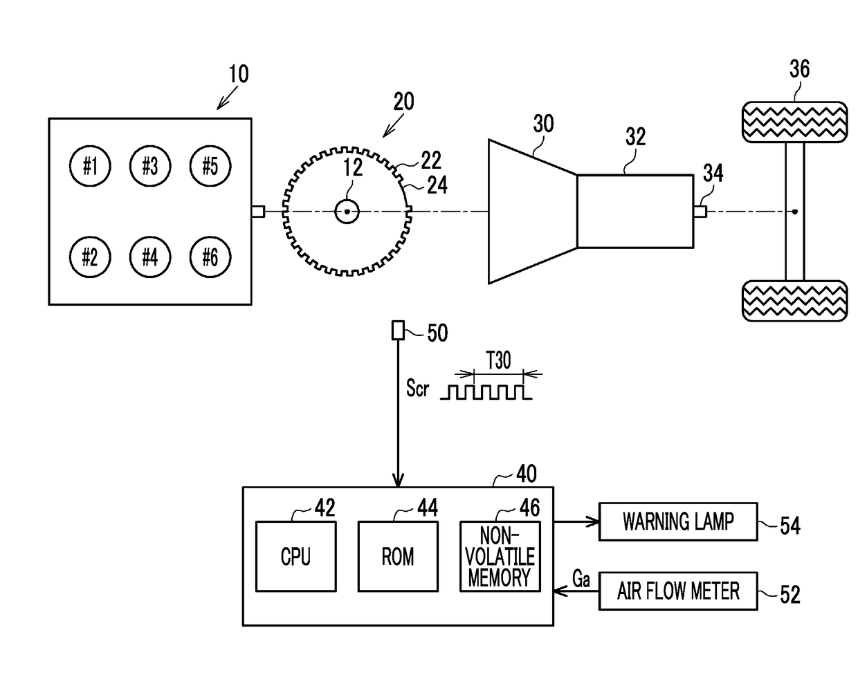
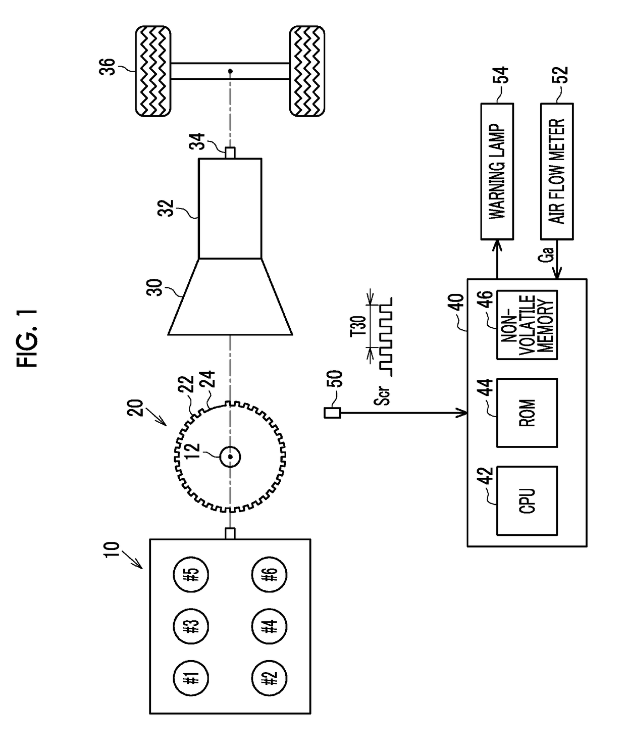
[0030]As illustrated in FIG. 1, an internal combustion engine 10 is a four-stroke engine having six cylinders. Particularly, the present embodiment is based on an internal combustion engine in which torque is adjusted with the amount of air filling each cylinder, like a gasoline engine. In the following description, cylinders #1, #2, #3, #4, #5, #6 are defined in accordance with the order of compression top dead center. That is, the cylinder that has the compression top dead center after the first cylinder #1 is the second cylinder #2.

[0031]A transmission device 32 can be connected to a crankshaft 12 of the internal combustion engine 10 through a torque converter 30. A drive wheel 36 is mechanically connected to an output shaft 34 of the transmission device 32.

[0032]The crankshaft 12 is joined with a crank rotor 20 in which a tooth portio...


PUM


Abstract

A misfire detection device includes an electronic control unit that calculates, based on a crank signal, a first component that is a first integer multiple frequency component of a combustion cycle related to a rotation change value and a second component that is a second integer multiple frequency component of the combustion cycle related to the rotation change value. The electronic control unit determines whether the second component has a maximum value or a minimum value in at least one of two phases of a phase where the first component has a maximum value and a phase where the first component has a minimum value. The electronic control unit determines that an interval between compression top dead centers of cylinders has continuous misfire based on a determination result of whether the second component has a maximum value or a minimum value.

Description

INCORPORATION BY REFERENCE[0001]The disclosure of Japanese Patent Application No. 2017-036334 filed on Feb. 28, 2017 including the specification, drawings and abstract is incorporated herein by reference in its entirety.BACKGROUND1. Technical Field[0002]The present disclosure relates to a misfire detection device for an internal combustion engine. The misfire detection device is applied to an internal combustion engine having a plurality of cylinders, and detects continuous misfire in at least one cylinder based on a rotation change value acquired by quantifying the difference in the rotational behavior of a crankshaft shown on a crank signal in a rotation angle interval that shows the influence of combustion in each of a pair of cylinders successive in time series order of compression top dead center.2. Description of Related Art[0003]For example, a device disclosed in Japanese Unexamined Patent Application Publication No. 2003-113736 (JP 2003-113736 A) detects misfires in an inter...

Claims


Application Information

Patent Timeline
IPC IPC(8): G01M15/11F02D41/14
CPCG01M15/11F02D41/1498F02D2200/1015F02B77/08F02D2200/101F02D2041/1432F02D2041/288
Inventor KATAYAMA, AKIHIRO
Owner TOYOTA JIDOSHA KK
Why Eureka
Try Eureka