Machining system for turbomachine dovetail

a technology of machining system and turbomachine, which is applied in the direction of turbines, manufacturing tools, machines/engines, etc., can solve the problems of high stress on the hole during operation, inefficient and costly delays, and difficult precision and control of the machining equipmen

Active Publication Date: 2018-09-13
GENERAL ELECTRIC CO
View PDF2 Cites 10 Cited by
  • Summary
  • Abstract
  • Description
  • Claims
  • Application Information

AI Technical Summary

Problems solved by technology

These holes can be subject to high stress during operation due the centrifugal force of the blades.
This can make precision and control of the machining equipment difficult, as the machining device (e.g., reamer) transitions from one material to another (e.g., low-alloy steel to martensitic stainless steel, or low alloy steel to titanium).
A...

Method used


Image

  • Machining system for turbomachine dovetail
  • Machining system for turbomachine dovetail
  • Machining system for turbomachine dovetail

Examples


Embodiment Construction

[0011]As indicated herein, the subject matter disclosed relates to turbomachinery. More particularly, the subject matter disclosed herein relates to performing maintenance (e.g., repair or replacement) on components in turbomachines.

[0012]In the following description, reference is made to the accompanying drawings that form a part thereof, and in which is shown by way of illustration specific example embodiments in which the present teachings may be practiced. These embodiments are described in sufficient detail to enable those skilled in the art to practice the present teachings and it is to be understood that other embodiments may be utilized and that changes may be made without departing from the scope of the present teachings. The following description is, therefore, merely illustrative.

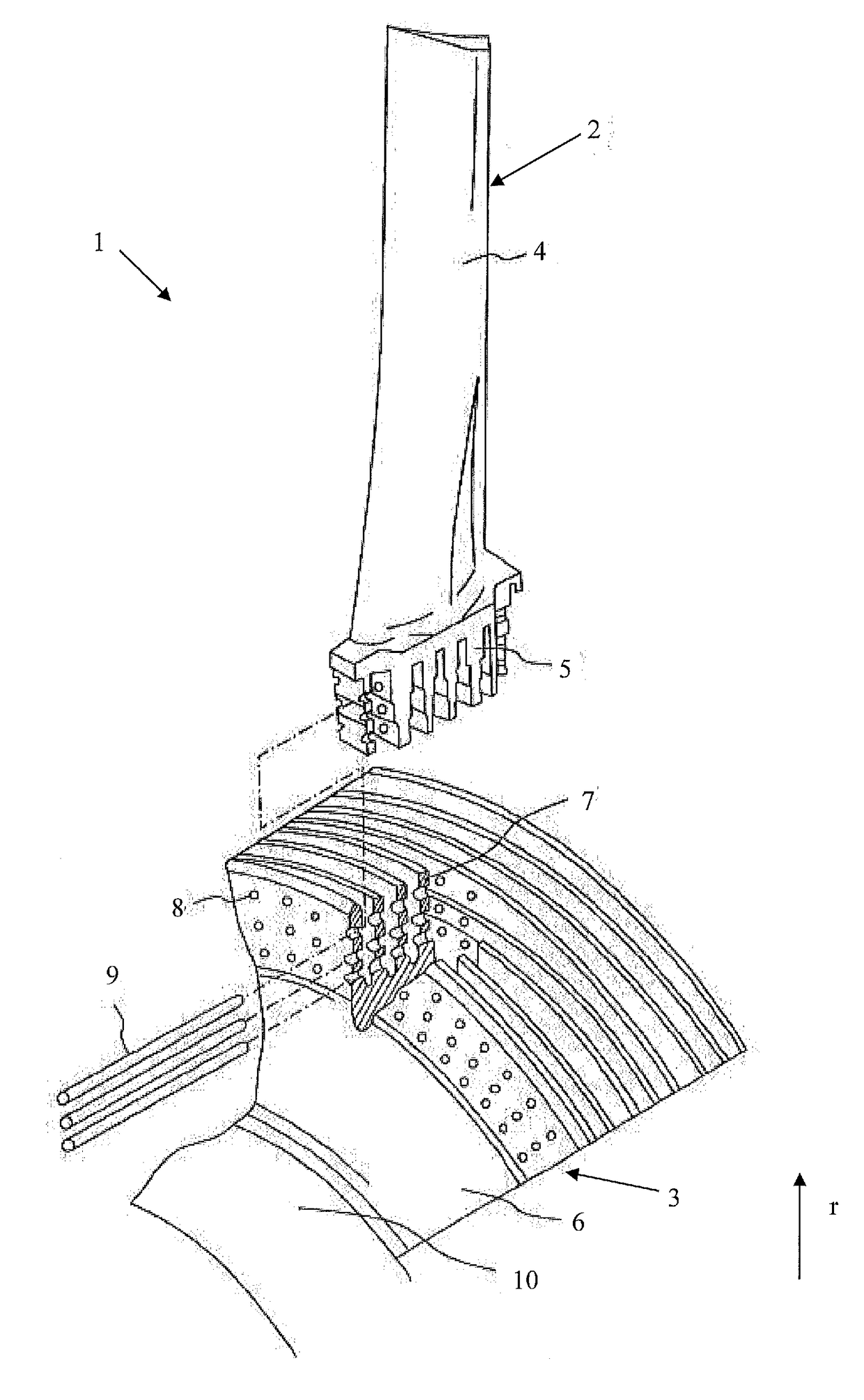
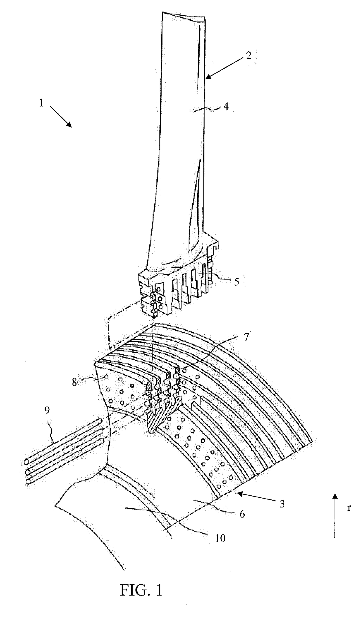
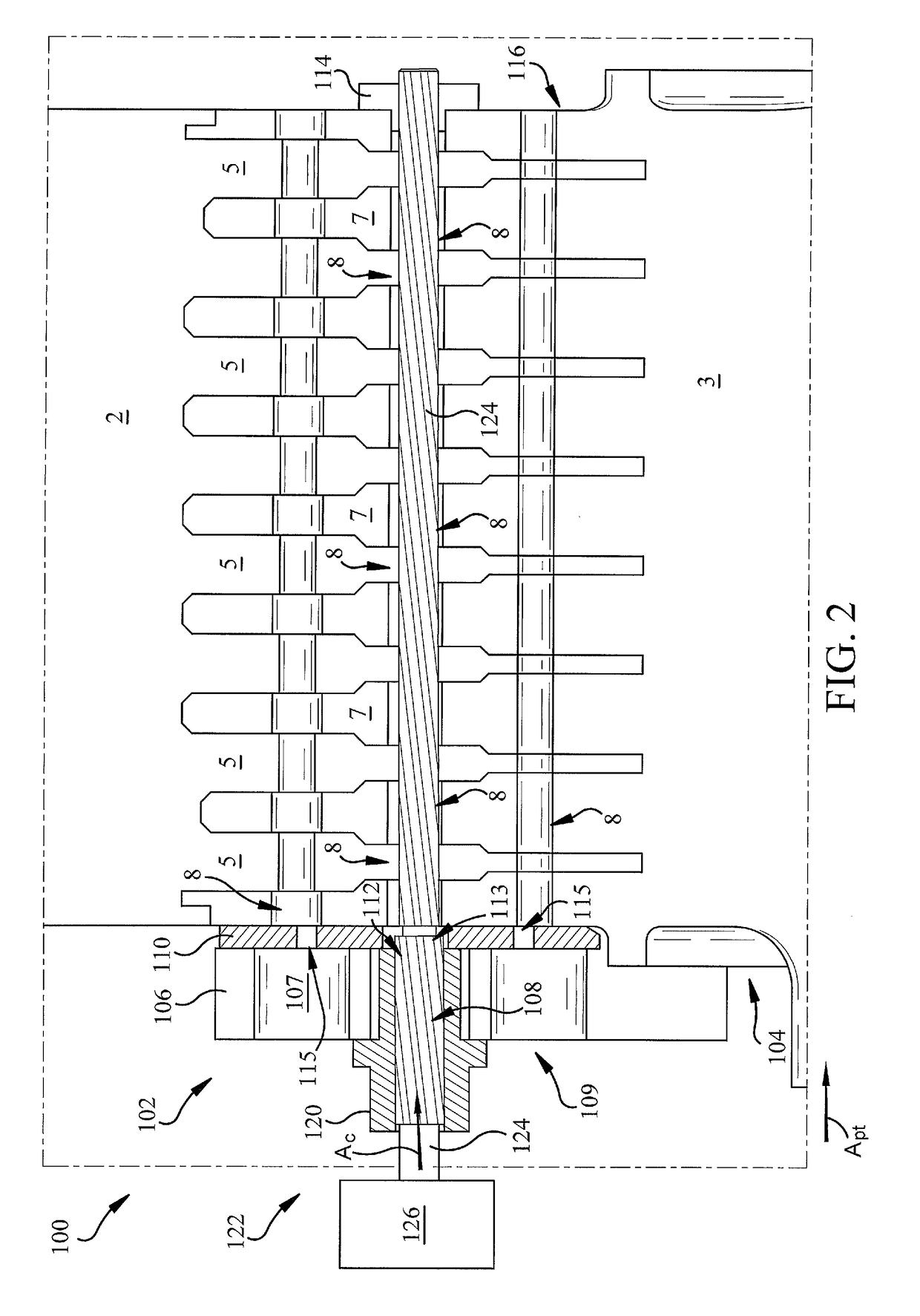
[0013]FIG. 1 is a schematic depiction showing a section of a turbomachine (turbine) blade attachment base (or simply, turbomachine) 1. Turbomachine 1 includes a turbine blade 2 (representing a se...


PUM

PropertyMeasurementUnit
Angleaaaaaaaaaa
Weightaaaaaaaaaa
Degree of freedomaaaaaaaaaa

Abstract

Various embodiments include a system for machining a hole in a turbine blade. The system can include: a mount for engaging a first side of a turbine rotor, the mount including: a drill plate for coupling with the first side of the turbine rotor, the drill plate having: a body; a feed opening on a first side of the body; a passage extending from the feed opening through the body; and a second opening on a second side of the body, the second opening coupled with the passage and positioned to align with the pre-formed hole in the turbine rotor; an alignment bushing for engaging the pre-formed hole in the rotor at a second side of the rotor; and a cutting device for extending through the body and alignment bushing, the cutting device for machining the hole in the blade, the cutting device aligned along a chamfer axis relative to a primary axis of the turbine rotor.

Description

FIELD OF THE INVENTION[0001]The subject matter disclosed herein relates to turbomachinery. More particularly, the subject matter disclosed herein relates to maintaining components in turbomachines.BACKGROUND OF THE INVENTION[0002]Turbomachinery, for example, steam turbomachinery such as steam turbines, are designed to have useable lifetimes that span for years, and even decades. During the course of their lifespan, these machines and their components require repair, replacement and / or maintenance.[0003]Some turbomachines utilize a radial-entry dovetail fit between the rotor and the blades. When replacing turbine blades in these configurations, the holes in new blades are match-machined (e.g., reamed) to existing holes in the turbine rotor. These holes can be subject to high stress during operation due the centrifugal force of the blades. Each row of blades has many (e.g., hundreds) of holes that are machined several times in order to best fit the existing holes in the rotor (e.g., w...

Claims


Application Information

Patent Timeline
IPC IPC(8): B23Q9/00B23K26/00B23K26/382B23H9/14B23D75/00F01D5/02F01D5/14F01D5/30
CPCB23Q9/0042B23K26/0096B23K26/382B23H9/14B23D75/00B23K2101/001F01D5/147F01D5/303F05D2220/31F05D2230/12F05D2230/13F01D5/02B23H1/00B23H7/28B23H9/10F01D5/005F01D5/3046F01D5/3053F01D25/285B23B47/28B23B2215/81B23B2247/12B23B2270/34
Inventor JOHNSON, PHILLIP CHARLESMALISON, ROBERT CHARLESSASSATELLI, JOHN MATTHEW
Owner GENERAL ELECTRIC CO
Why Eureka
Try Eureka