High-pressure tank

Active Publication Date: 2018-09-13
TOYOTA JIDOSHA KK
View PDF9 Cites 7 Cited by
  • Summary
  • Abstract
  • Description
  • Claims
  • Application Information

AI Technical Summary

Benefits of technology

[0014]According to the present disclosure, a high-pressure tank can be obtained in which a liner can be formed using the conventionally used material a decrease in the volumetric efficiency within the liner can be suppressed, and direct influence of heat generated due to adiabatic compression of gas filling the tank on the liner can be significantly alleviated. Therefo

Problems solved by technology

Due to such temperature rise, there is a possibility that the constituent members of the high-pressure tank, in particular, t

Method used


Image

  • High-pressure tank
  • High-pressure tank
  • High-pressure tank

Examples


Example

First Embodiment

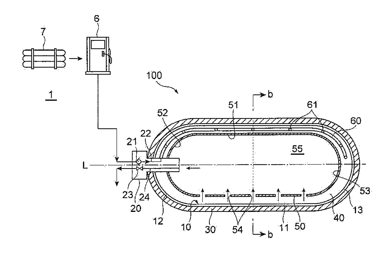
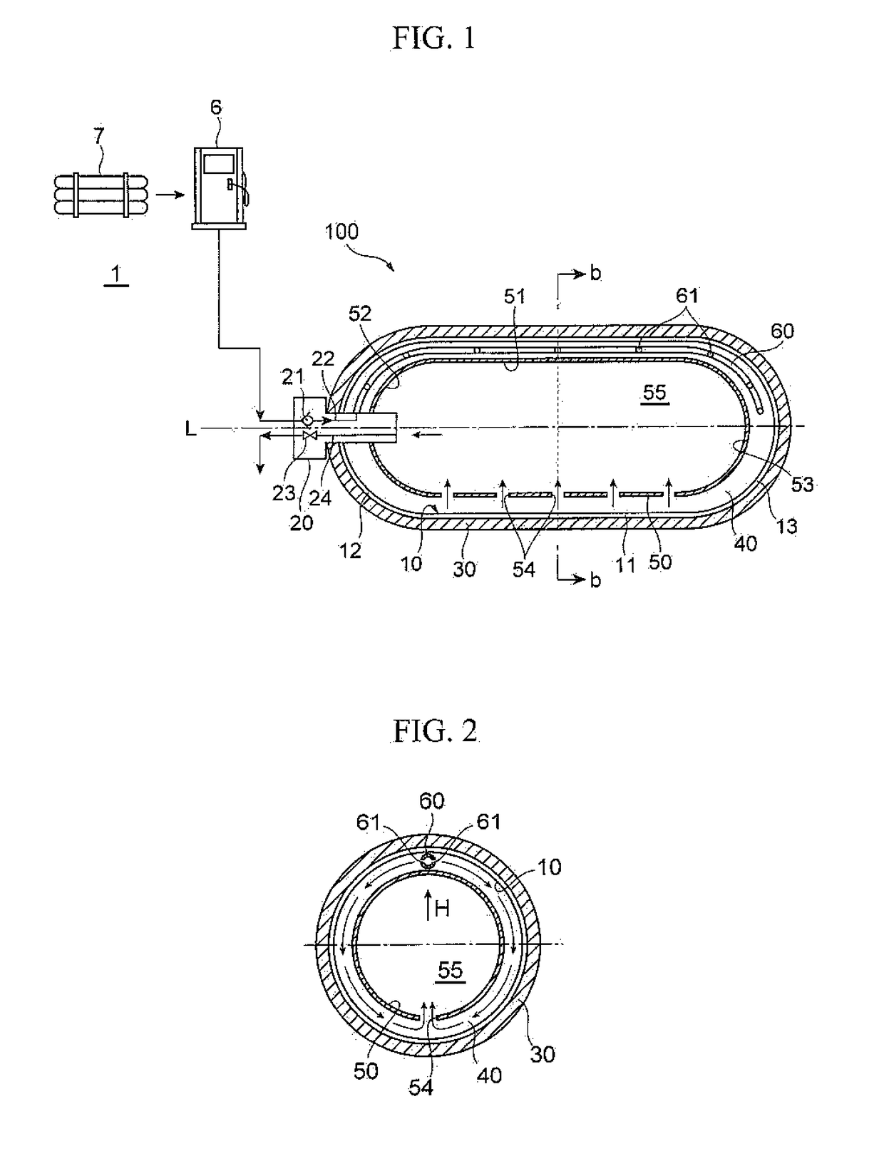
[0024]FIG. 1 is a view of a first embodiment of a high-pressure tank in accordance with the present disclosure. Specifically, FIG. 1 is a cross-sectional view along the central axis line, and FIG. 2 is a cross-sectional view along a direction orthogonal to the central axis line, that is, a cross-sectional view along line b-b of FIG. 1.

[0025]The high-pressure tank 100 has a liner 10 made of a material through which gas stored in the tank does not permeate. The liner 10 includes a cylindrical body 11, a first dome portion 12 in a hemispherical shape integrally formed with one end of the body 11, and a second dome portion 13 in a hemispherical shape integrally formed with the other end of the body 11. A valve device 20 is attached to the center of the first dome portion 12. The material of the liner 10 may be either a metallic material or a resin material.

[0026]The valve device 20 is adapted to allow the inside of the liner 10 and the outside of the tank to communicate ...

Example

Second Embodiment

[0051]FIG. 7 shows another embodiment of a high-pressure tank. FIG. 7 is a cross-sectional view corresponding to FIG. 2 showing the cross-section of the high-pressure tank 100 of the first embodiment. The high-pressure tank 200 shown in FIG. 7 has a different configuration from the high-pressure tank 100 of the first embodiment in that the through-holes 54 in the inner container 50 are not only formed in the lowermost portion of the inner container 50 in the vertical direction like the high-pressure tank 100 of the first embodiment shown in FIG. 1 but are also dispersed across the entire region at a level lower than the central line P of the inner container 50 in the vertical direction when the high-pressure tank 200 is laid on its side. The other configurations are the same as those of the high-pressure tank 100 of the first embodiment, and the same members are denoted by the same reference numerals. The high-pressure tank 200 in this embodiment is advantageous in ...

Example

Third Embodiment

[0052]FIG. 8 shows the cross-section of a high-pressure tank 300 of a third embodiment along its central axis line L. The high-pressure tank 300 shown in FIG. 8 differs from the high-pressure tank 100 of the first embodiment in that the high-pressure tank 300 does not have the pipe 60; the through-holes 54 in the inner container 50 are formed in an end region of the inner container 50 on the side opposite to an end at which the valve device 20 is attached, that is, in the aforementioned second dome portion 53; the valve device 20 has two or more gas outlets of the first communication channel 22 with the check valve 21; and the gas outlets are formed radially around the central axis line L. The other configurations are the same as those of the high-pressure tank 100 of the first embodiment, and the same members are denoted by the same reference numerals.

[0053]The high-pressure tank 300 in this embodiment can also obtain the same operational effects of the high-pressur...


PUM

PropertyMeasurementUnit
Temperatureaaaaaaaaaa
Pressureaaaaaaaaaa
Efficiencyaaaaaaaaaa

Abstract

A high-pressure tank in which a liner can be formed using the conventionally used material, a decrease in the volumetric efficiency within the liner can be suppressed, and influence of a temperature rise due to adiabatic compression on the liner can be significantly alleviated. The tank includes a liner that suppresses permeation of gas; a valve device that allows the inside of the liner and the outside of the tank to communicate with each other and blocks communication therebetween; and an inner container with a through-hole disposed within the liner such that a gap is formed between the inner container and an inner periphery of the liner. The first communication channel of the valve device connects with a pipe extending in the gap and having holes therein. Gas supplied to the valve device is supplied into the gap from the holes in the pipe, and fills the inner container in a high-pressure state from the gap through the through-hole in the inner container.

Description

CROSS REFERENCE TO RELATED APPLICATIONS[0001]The present application claims priority from Japanese patent application JP 2017-045421 filed on Mar. 9, 2017, the content of which is hereby incorporated by reference into this application.BACKGROUNDTechnical Field[0002]The present disclosure relates to a high-pressure tank for storing gas in a high-pressure state therein.Background Art[0003]High-pressure tanks for storing gas in a high-pressure state therein are known. In addition, fuel-cell cars having mounted thereon high-pressure hydrogen gas tanks, which store hydrogen gas as fuel gas in a high-pressure state therein, are also known.[0004]Usually, this type of high-pressure tank includes, as described in JP 2008-232243 A, for example, a liner that serves the function of a barrier layer to suppress permeation of gas to be stored in the tank, a fiber-reinforced resin layer for securing the strength of the high-pressure tank by covering the outer periphery of the liner, and a valve dev...

Claims


Application Information

Patent Timeline
IPC IPC(8): F17C1/04F17C13/04
CPCF17C1/04F17C13/04F17C2201/0109F17C2260/01F17C1/00F17C2201/056F17C2201/058F17C2203/0604F17C2203/0663F17C2205/0305F17C2205/0397F17C2221/012F17C2223/0123F17C2223/036F17C2260/037F17C2270/0184Y02E60/32
Inventor KONDO, TOSHIYUKI
Owner TOYOTA JIDOSHA KK
Why Eureka
Try Eureka