Cooling system for rotorcraft laser system

Active Publication Date: 2018-09-13
SIKORSKY AIRCRAFT
View PDF4 Cites 0 Cited by
  • Summary
  • Abstract
  • Description
  • Claims
  • Application Information

AI Technical Summary

Problems solved by technology

Use of turreted guns on rotorcraft can be limited by the number of rounds carried on the aircraft, which drives the desire for laser weapons.
While implementation of fiber lasers improves on the issue associated with the ammunition storage aspect, challenges with fiber laser

Method used


Image

  • Cooling system for rotorcraft laser system
  • Cooling system for rotorcraft laser system
  • Cooling system for rotorcraft laser system

Examples


Example

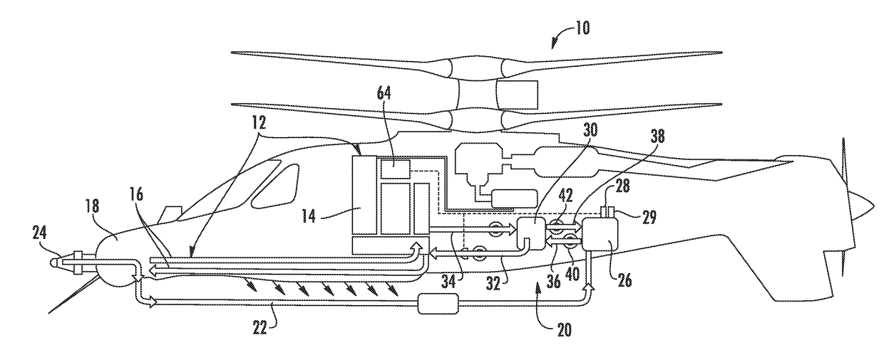
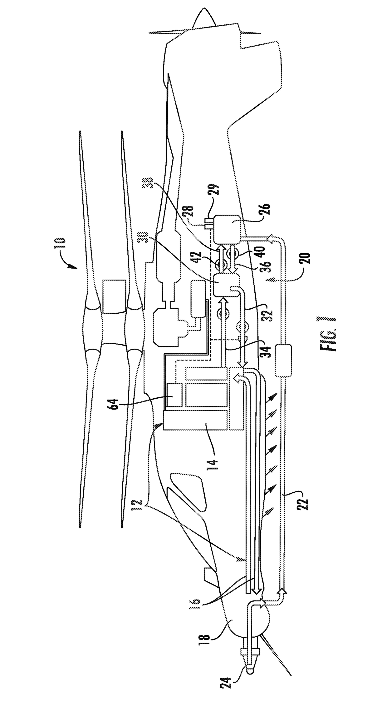
[0025]Referring to FIG. 1, illustrated is a rotary wing aircraft 10 having a laser system 12. It is to be understood that the term “helicopter” is a sub-class of the term “rotorcraft,” but the terms may be used interchangeably herein. Although a particular helicopter configuration is illustrated and described in the disclosed embodiment, other vehicles with integrated laser systems may also benefit from the embodiments described herein. The laser system 12 facilitates generation of a laser onboard the helicopter 10 and guided control of the laser away from the helicopter 10. The laser system 12 is beneficial in numerous applications, such as tactical weaponry, for example.

[0026]The laser system 12 includes a laser generating assembly 14 located onboard the helicopter 10. The location of the laser generating assembly 14 may vary depending upon the particular embodiment of the helicopter 10. The laser generating assembly 14 includes a plurality of components and subassemblies that in ...


PUM


Abstract

A cooling system for a rotorcraft laser system is provided. The cooling system includes at least one laser carrying component operatively coupling a laser turret and a laser generating assembly. The cooling system also includes at least one fuel line fluidly coupled to a fuel tank containing a fuel. The cooling system further includes a heat exchanger containing a portion of the laser carrying component and the fuel line to transfer heat therebetween to cool the laser carrying component.

Description

BACKGROUND OF THE INVENTION[0001]The embodiments herein generally relate to rotorcraft laser systems and, more particularly, to a cooling system for such laser systems, as well as a method of cooling rotorcraft laser systems.[0002]Fiber lasers are increasingly becoming potent tactical weapons on vehicles. In one example, fiber lasers are employed on an aircraft, such as a helicopter. Use of turreted guns on rotorcraft can be limited by the number of rounds carried on the aircraft, which drives the desire for laser weapons. While implementation of fiber lasers improves on the issue associated with the ammunition storage aspect, challenges with fiber laser systems are present. In particular, some fiber laser systems waste significant energy in the form of heat. This wasted energy can be up to or even above 70% of the total energy. Therefore, waste heat dissipation of a laser system onboard a tactical rotorcraft poses significant challenges and limits the efficient use of such systems ...

Claims


Application Information

Patent Timeline
IPC IPC(8): H01S3/042B64C27/04H01S3/067
CPCH01S3/042B64C27/04H01S3/06704H01S3/0407
Inventor SMILEY, ALFRED RUSSELLKOLIAIS, PANAGIOTISLAUDER, TIMOTHY FREDALBER, MARK R.
Owner SIKORSKY AIRCRAFT
Why Eureka
Try Eureka