Endoscope position specifying device, method, and program

a technology of endoscope and position, which is applied in the field of endoscope position specifying device, method and program, can solve the problems of difficult to make the distal end of the endoscope reach a target position, difficult to ascertain which position in the tubular structure the endoscope image represents, and accumulate errors as time passes. , to achieve the effect of accurate calculation, accurate calculation of the absolute position of the endoscope, and low accuracy

Inactive Publication Date: 2018-09-20
FUJIFILM CORP
View PDF2 Cites 4 Cited by
  • Summary
  • Abstract
  • Description
  • Claims
  • Application Information

AI Technical Summary

Benefits of technology

[0017]According to the invention, the amount of movement of the endoscope during a period from the acquisition of the reference endoscope image to the acquisition of the latest endoscope image is calculated based on the sequentially acquired endoscope images, the position of the endoscope is estimated based on the calculated amount of movement, and the first certainty factor indicating the possibility of presence of the endoscope within the tubular structure is calculated based on the estimated position. Then, matching between the image of the tubular structure and the endoscope image is performed at each of a plurality of positions within the tubular structure, so that the second certainty factor indicating the possibility of presence of the endoscope is calculated at each of the plurality of positions. Using the first certainty factor, a relative change in the position of the endoscope from the acquisitio...

Problems solved by technology

For this reason, it is difficult to ascertain which position in the tubular structure the endoscope image represents.
In particular, since a bronchial endoscope has a small diameter and accordingly has a narrow field of view, it is difficult to make the distal end of the endoscope reach a target position.
In addition, although the current position of the endoscope can ...

Method used


Image

  • Endoscope position specifying device, method, and program
  • Endoscope position specifying device, method, and program
  • Endoscope position specifying device, method, and program

Examples


first embodiment

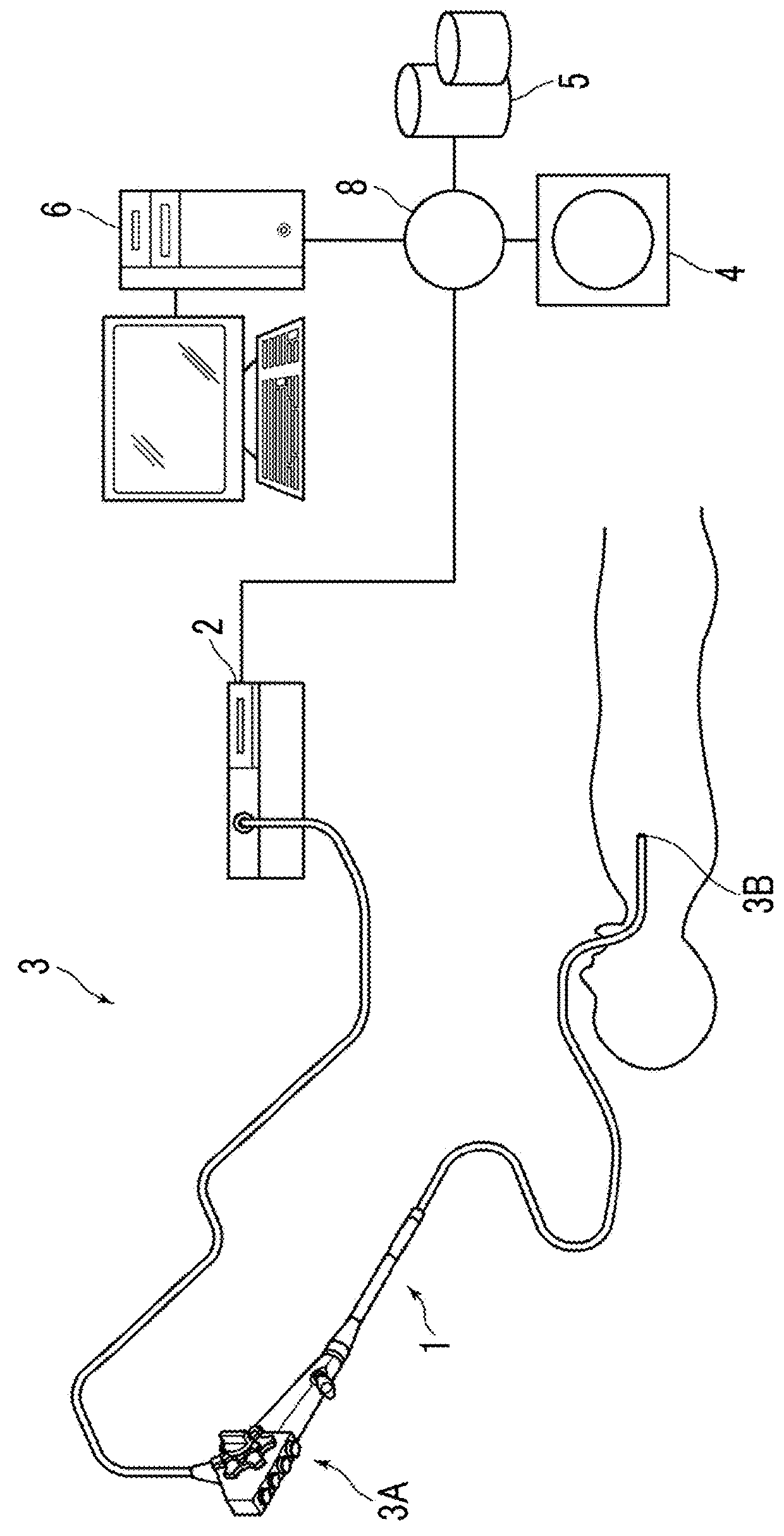
[0036]Hereinafter, embodiments of the invention will be described with reference to the accompanying diagrams. FIG. 1 is a hardware configuration diagram showing the outline of a diagnostic assistance system to which an endoscope position specifying device according to the invention is applied. As shown in FIG. 1, in this system, an endoscope apparatus 3, a three-dimensional image capturing apparatus 4, an image storage server 5, and an endoscope position specifying device 6 are connected to each other in a communicable state through a network 8.

[0037]The endoscope apparatus 3 includes an endoscope scope 1 for imaging the inside of a tubular structure of a subject, a processor device 2 for generating an image of the inside of the tubular structure based on a signal obtained by imaging, and the like.

[0038]The endoscope scope 1 is obtained by continuously attaching an insertion part, which is inserted into the tubular structure of the subject, to an operation unit 3A, and is connected...

second embodiment

[0090]FIG. 14 is a diagram showing the position of the endoscope estimated based on a plurality of reference endoscope image in the Here, it is assumed that two endoscope positions are estimated based on two reference endoscope images. For example, it is assumed that one of the reference endoscope images is the second endoscope image Gt-1 similar to the above embodiment and the other one is an endoscope image Gt-10 10 frames before the first endoscope image Gt.

[0091]The first certainty factor calculation unit 23 estimates the position of the endoscope distal end 3B based on the first endoscope image Gt and the second endoscope image Gt-1. This is assumed to be a first position 64 of the endoscope distal end 3B. The first certainty factor calculation unit 23 estimates the position of the endoscope distal end 3B based on the first endoscope image Gt and the endoscope image Gt-10. This is assumed to be a second position 65 of the endoscope distal end 3B. In this case, at each of the f...

third embodiment

[0100]In the third embodiment described above, a normal endoscope image is specified by determining whether or not a hole portion is detected in the endoscope image. However, a normal endoscope image may be specified from sequentially acquired endoscope images using a discriminator learned to discriminate between a normal endoscope image and an abnormal endoscope image.

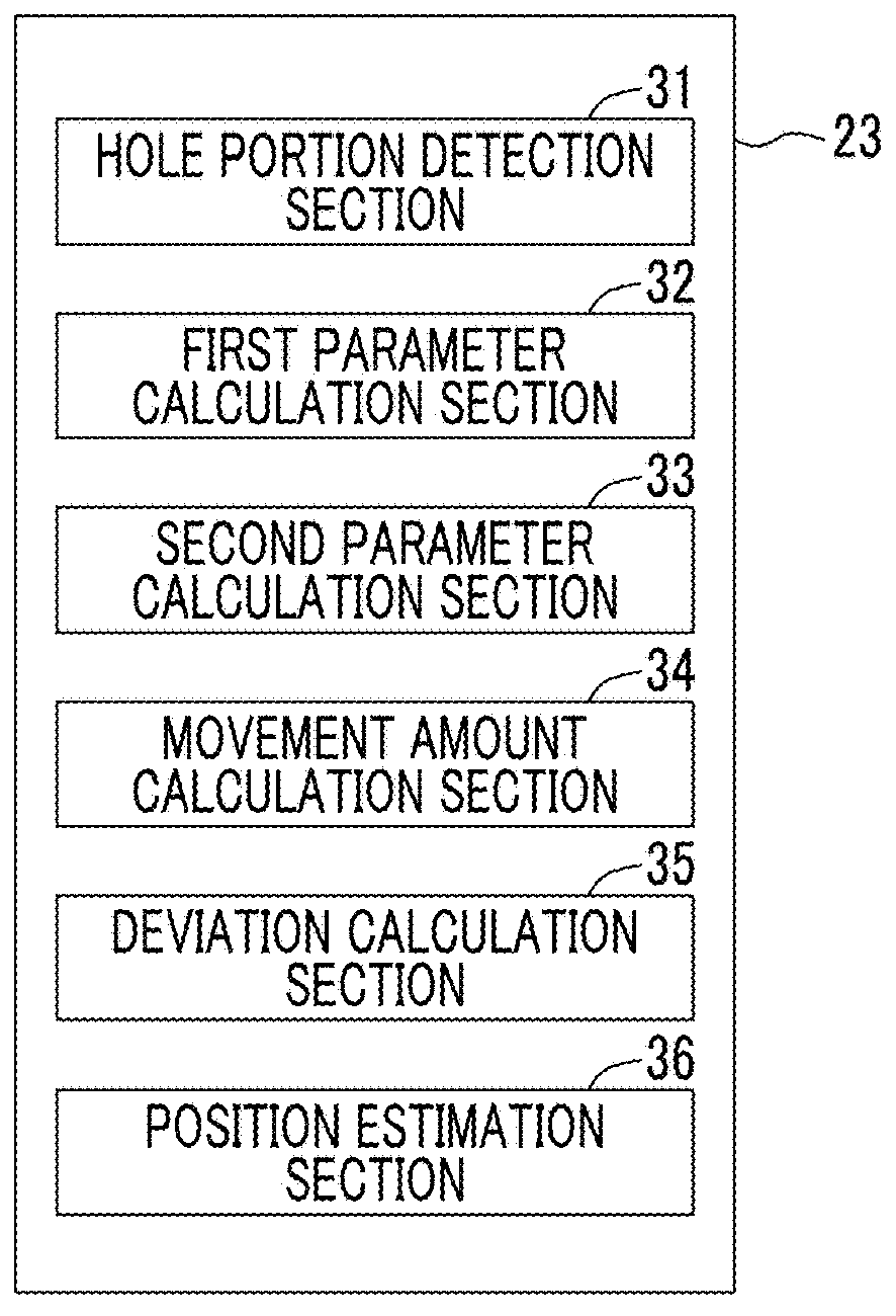
[0101]In each embodiment described above, the hole portion detection section 31 of the first certainty factor calculation unit 23 detects a hole portion from each of the first and second endoscope images. However, a hole portion may also be detected from one of the first and second endoscope images Gt and Gt-1. For example, in a case where a hole portion is detected only from the first endoscope image Gt, an image in which the detected hole portion is cut out or an image in which the weight of the hole portion is increased can be generated, and the first parameter P1 and the second parameter P2 can be calculated by us...


PUM


Abstract

An image acquisition unit sequentially acquires an endoscope image of a tubular structure having a plurality of branch structures, and an image generation unit generates an image of the tubular structure. A first certainty factor calculation unit calculates a first certainty factor indicating a possibility of presence of the endoscope within the tubular structure. A second certainty factor calculation unit calculates a second certainty factor indicating a possibility of presence of the endoscope by performing matching between the image of the tubular structure and each of the endoscope images at each of a plurality of positions within the tubular structure. A current position specifying unit specifies the current position of the endoscope based on the first and second certainty factors.

Description

CROSS REFERENCE TO RELATED APPLICATIONS[0001]The present application claims priority under 35 U.S.C. § 119 to Japanese Patent Application No. 2017-051506 filed on Mar. 16, 2017. The above application is hereby expressly incorporated by reference, in its entirety, into the present application.BACKGROUNDField of the Invention[0002]The present invention relates to an endoscope position specifying device, method, and program for specifying the position of an endoscope in a tubular structure having branch structures, such as a bronchus, in the case of observing the tubular structure by inserting the endoscope into the tubular structure.Description of the Related Art[0003]In recent years, a technique of observing or treating a tubular structure, such as a bronchus and a large intestine of a patient, using an endoscope has been drawing attention. However, in the endoscope image, an image in which the color or texture of the inside of the tubular structure is clearly expressed by an imaging...

Claims


Application Information

Patent Timeline
IPC IPC(8): A61B5/06A61B1/00A61B1/04A61B1/267
CPCA61B5/066A61B1/00009A61B1/0005A61B1/00006A61B1/04A61B1/2676A61B1/000094A61B1/009
Inventor KITAMURA, YOSHIRO
Owner FUJIFILM CORP
Why Eureka
Try Eureka