Magnetic control water resistance rowing machine

a water resistance rowing machine and magnetic control technology, applied in the field of fitness devices, can solve the problems of inconvenience and complex structure, and achieve the effect of reducing the number of strokes and improving the efficiency of the strok

Active Publication Date: 2018-09-27
AMOY YG SPORTS TECH CO LTD
View PDF22 Cites 13 Cited by
  • Summary
  • Abstract
  • Description
  • Claims
  • Application Information

AI Technical Summary

Benefits of technology

[0032]FIG. 11 is a schematic view of showing the effect of the use of the

Problems solved by technology

When the damping size needs to be adjusted, it is achieved by adjusting the level of the water level of the water resistance device or by adjusting the external friction mechanism to adjust the damping size, thus b

Method used


Image

  • Magnetic control water resistance rowing machine
  • Magnetic control water resistance rowing machine
  • Magnetic control water resistance rowing machine

Examples


embodiment 1

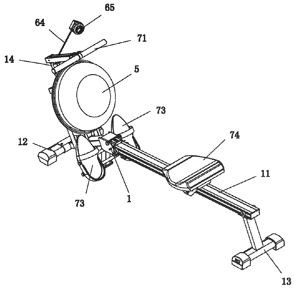
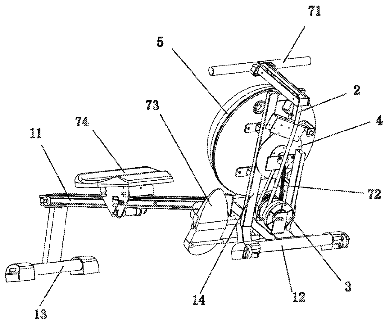
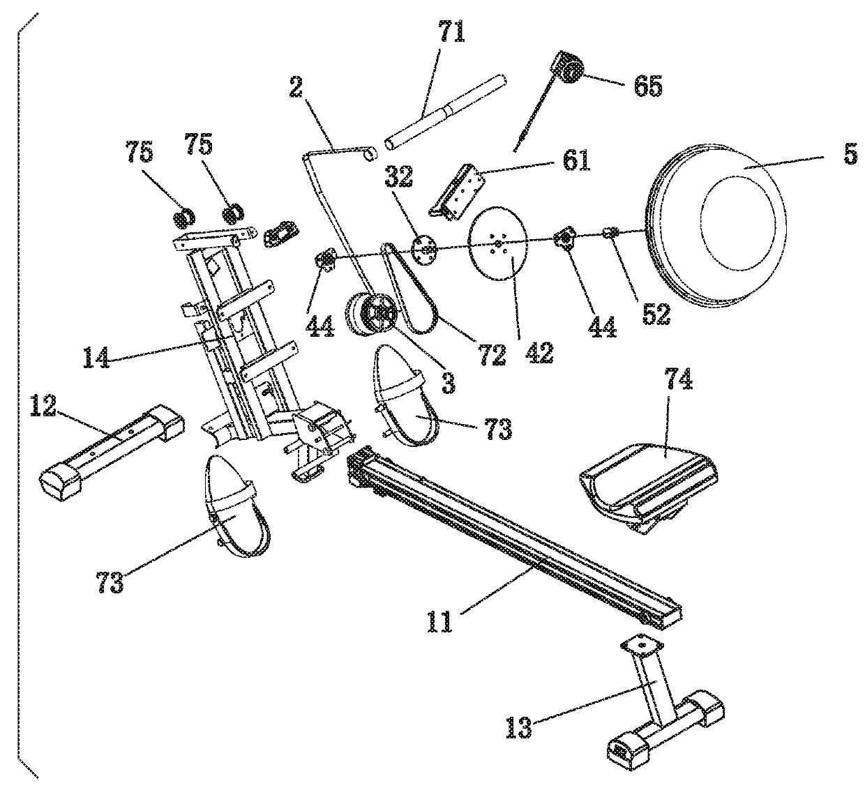
[0034]Referring to FIGS. 1 to 8, a magnetic control water resistance rowing machine according to the present invention comprises a main rack 1, a ribbon 2, a ribbon recycling plate set 3, an aluminum wheel water resistor set, a magnetic plate set 6 and a seat cushion 74; one end of the ribbon 2 is connected to the handle 71, and the other end of the ribbon 2 is connected to the ribbon recycling plate set 3, which is mounted on the main rack 1 by a torsion spring in order to recycle the ribbon 2 when the ribbon 2 is loosened; said aluminum wheel water resistor set comprises an aluminum wheel set 4 and a water resistance device 5; the aluminum wheel set 4 is mounted on the main rack 1 and is in is in a position where the aluminum wheel set 4 cooperates with the ribbon recycling plate set 3; and the ribbon recycling plate set 3 is connected to the aluminum wheel set 4 drive; the water resistance device 5 is mounted on the main rack 1 and is in a position where the water resistance devi...

embodiment 2

[0047]Referring to FIGS. 9 to 11, a magnetic control water resistance rowing machine according to the present invention differs from Embodiment 1 in that the seat cushion has a different structure. The seat cushion 74 of the present embodiment includes a seat plate 741, a chute 742 provided at the bottom of the seat plate and a backrest 743, the backrest 743 is hinged to the rear end of the seat plate 741 by a torsion spring. Wherein the chute 742 is fitted to the slide rail engagement 11 of the main rack 1.

[0048]Between the seat plate 741 and the chute 742 is also provided a connecting member 744, the backrest 743 is hingedly connected to the rear end of the connecting member 744 by a torsion spring. The backrest 743 includes a backrest lever 7431 and a plurality of cross bars 7432, the bottom end of a backrest lever 7431 is hinged at the rear end of the connecting member 744 by a torsion spring, and a plurality of cross bars 7432 are fixed to both sides of the backrest lever 7431,...


PUM


Abstract

A magnetic control water resistance rowing machine has a main rack, a ribbon, a ribbon recycling plate set, an aluminum wheel water resistance device set, a magnetic plate set and a seat cushion. The ribbon is connected with a ribbon recycling plate. The ribbon recycling plate set is mounted on the main rack by a torsion spring to recycle the ribbon when the ribbon is loosened; the aluminum wheel water resistance device set is mounted on the main rack and the aluminum wheel water resistance device set cooperates with the ribbon recycling plate set. The ribbon recycling plate set is connected to the aluminum wheel water resistance set drive; the magnetic plate is mounted on the main rack. The magnetic plate cooperates with the aluminum wheel water resistance. The main rack has a slide rail engagement and the seat cushion is slidably engaged with the slide rail engagement.

Description

FIELD OF INVENTION[0001]The present invention relates to a fitness device, and more particularly, to a magnetic control water resistance rowing machine capable of simulating the boating movementBACKGROUND OF INVENTION[0002]The rowing machine is also called the rowing boat, is a kind of fitness equipment to simulate the boating movement, has a better effect on the leg, waist, upper limbs, chest, back muscles. A conventional rowing boat (as disclosed in bulletin No. CN304082437S) adopts a water damper as a damping wheel, wherein a handle is usually connected with a ribbon, a ribbon is connected to a pulley, a pulley is connected to a water resistance device. When the damping size needs to be adjusted, it is achieved by adjusting the level of the water level of the water resistance device or by adjusting the external friction mechanism to adjust the damping size, thus bringing about the drawback of inconvenience. On the other hand, the prior art of such a rowing boat usually adopts ela...

Claims


Application Information

Patent Timeline
IPC IPC(8): A63B22/00A63B21/00
CPCA63B22/0076A63B21/00192A63B2022/0079A63B2209/08A63B21/0051A63B21/0084A63B21/023A63B21/153A63B22/0087A63B23/0211A63B23/0233A63B2022/0035
Inventor HOU, YANWEISUN, YU
Owner AMOY YG SPORTS TECH CO LTD
Why Eureka
Try Eureka