Plasma generation method, plasma processing method using the same and plasma processing apparatus

Inactive Publication Date: 2018-09-27
TOKYO ELECTRON LTD
View PDF17 Cites 126 Cited by
  • Summary
  • Abstract
  • Description
  • Claims
  • Application Information

AI Technical Summary

Benefits of technology

[0008]More specifically, the embodiments of the present disclosure may provide a plasma generation method and plasma processing method using the same, and a plasm

Problems solved by technology

The technique disclosed in Japanese Laid-Open Patent Application Publication No 2015-154025 introduces an ignition sequence that facilitates the ignition of plasma after a stop for a long period of time because the ignition of plasma is likely to be difficult when the plasma processing apparatus is stopped for a long period of time for maintenance and the like.
However, although Japanese Laid-Open Patent Application Publication No 2015-154025 discloses the sequence that facilitates the ignition of plasma after the stop for a long period of time, Japanese Laid-Open Patent Application Publication

Method used


Image

  • Plasma generation method, plasma processing method using the same and plasma processing apparatus
  • Plasma generation method, plasma processing method using the same and plasma processing apparatus
  • Plasma generation method, plasma processing method using the same and plasma processing apparatus

Examples


first embodiment

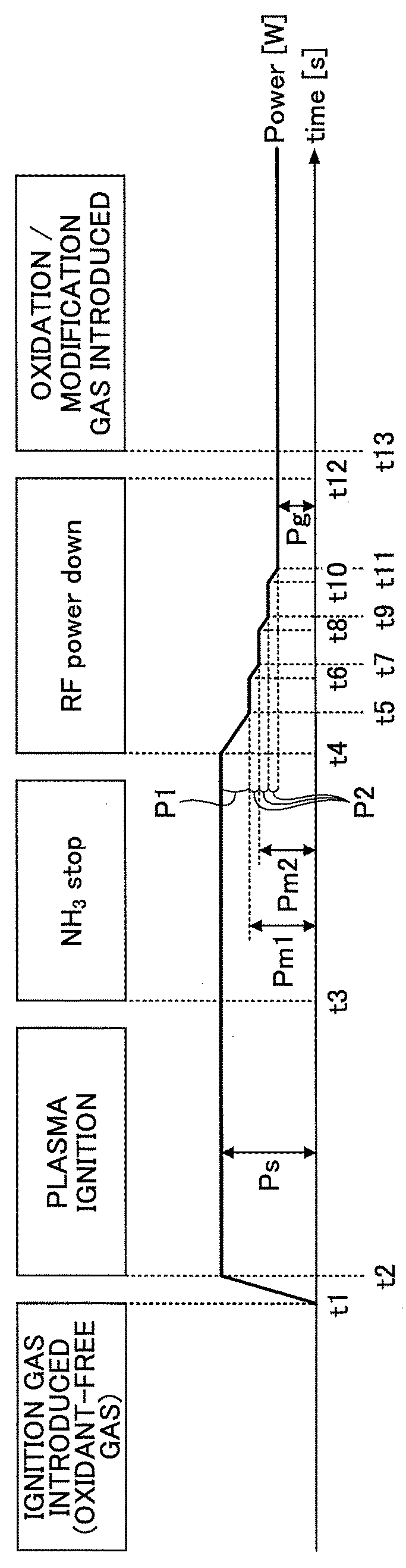
[0028]FIG. 1 is a sequence diagram illustrating an example of a plasma generation method according to a first embodiment of the present disclosure. In FIG. 1, a horizontal axis shows time [s], and a vertical axis shows output power [W] of a radio frequency power source supplied to a plasma generator. Although the plasma generator and the radio frequency power source are not illustrated in FIG. 1, a variety of plasma generators and radio frequency power sources can be used.

[0029]As illustrated in FIG. 1, an ignition gas is introduced at time t1. A gas other than an oxidation gas, that is, a gas that does not contain an oxygen atom, is selected as the ignition gas. For example, the ignition gas may be ammonia (NH3) gas. In this embodiment, an example of using ammonia gas as the ignition gas is described below.

[0030]Here, the reason why a non-oxidation gas that does not contain the oxygen atom is selected as the ignition gas is because when a film other than an oxide film is formed on ...

second embodiment

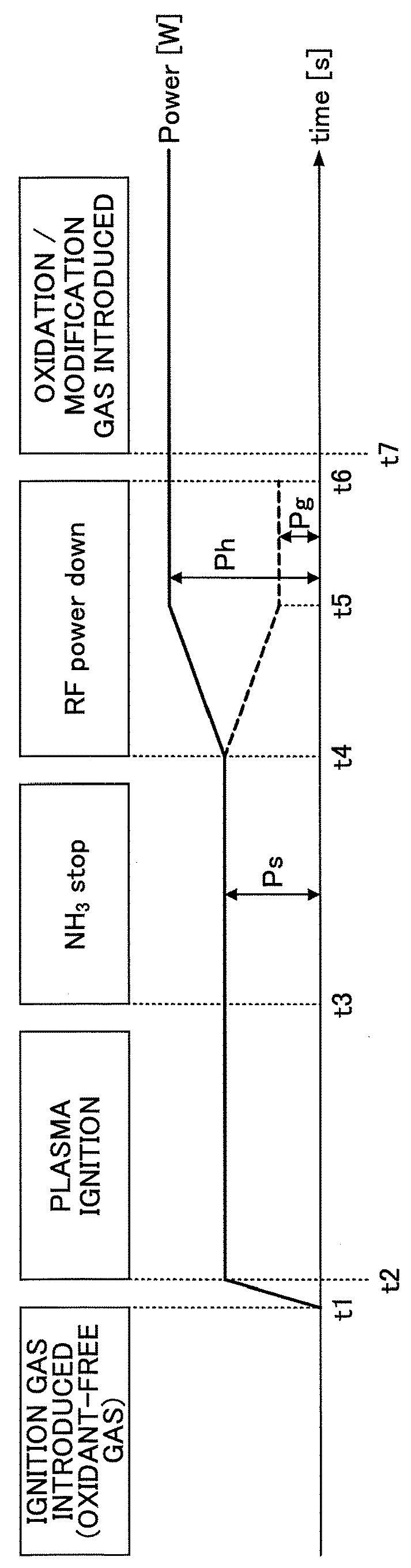
[0052]FIG. 5 is a diagram illustrating an example of a plasma generation method according to a second embodiment of the present disclosure. As illustrated in FIG. 5, in the plasma generation method according to the second embodiment, power P3 is the lowest amount of decreasing power. The power reaches intermediate power Pm1 by decreasing the power from normal power Ps by the power P1, and then reaches intermediate power Pm2 by decreasing the power by power P2. Thus, the intermediate power may be divided into 2-stage intermediate power Pm1 and Pm2. The power P2 is set at a value that is lower than the power P1 and higher than the power P3. Such a setting allows the intermediate power Pm2 to be set at a value lower than the intermediate power Pm1 and the power Pm2 of the first embodiment. In this case, the intermediate power Pm2 is set at a value having a level that is not reliably extinguished when the power is decreased in two stages.

[0053]For example, when the normal power Ps is se...

third embodiment

[0056]In a third embodiment of the present disclosure, an example of applying the plasma generation methods according to the first and second embodiments to a plasma processing apparatus is described below.

[0057]FIG. 6 is a schematic vertical cross-sectional view illustrating an example of a plasma processing apparatus according to an embodiment of the present disclosure. FIG. 7 is a schematic plan view illustrating an example of the plasma processing apparatus according to the embodiment. In FIG. 7, for convenience of explanation, a depiction of a top plate 11 is omitted.

[0058]As illustrated in FIG. 6, the plasma processing apparatus of the embodiment includes a vacuum chamber 1 having a substantially circular planar shape, and a susceptor 2 that is disposed in the vacuum chamber 1 such that the rotational center of the susceptor 2 coincides with the center of the vacuum chamber 1. The susceptor 2 rotates wafers W placed thereon by rotating around its rotational center.

[0059]The va...


PUM

PropertyMeasurementUnit
Poweraaaaaaaaaa
Poweraaaaaaaaaa
Plasma poweraaaaaaaaaa

Abstract

A plasma generation method is provided to generate and maintain plasma by supplying a predetermined power that is lower than a normal power to a plasma generator. Plasma of an ignition gas is generated by supplying the normal power to the plasma generator. A power input to the plasma generator is decreased by a first power that is smaller than a difference between the normal power and the predetermined power. The power input to the plasma generator is decreased by a second power that is smaller than the first power. Decreasing the power input to the plasma generator by the second power is performed after decreasing the power input to the plasma generator by the first power and is repeated a plurality of times.

Description

CROSS-REFERENCE TO RELATED APPLICATION[0001]The present application is based upon and claims the benefit of priority of Japanese Patent Application No. 2017-060556, filed on Mar. 27, 2017, the entire contents of which are incorporated herein by reference.BACKGROUND OF THE INVENTION1. Field of the Invention[0002]The present invention relates to a plasma generation method, a plasma processing method using the same and a plasma processing apparatus.2. Description of the Related Art[0003]Japanese Laid-Open Patent Application Publication No. 2015-154025 discloses a method for operating a plasma processing apparatus that generates plasma by supplying a first radio frequency power having a predetermined output to an electrode and processes an object with the plasma. In the method, when a period of time from the end of previous operation of the plasma processing apparatus exceeds a predetermined period of time, the plasma processing apparatus starts a plasma process after performing a charg...

Claims


Application Information

Patent Timeline
IPC IPC(8): H01J37/32C23C16/455C23C16/52
CPCH01J37/32137C23C16/45536C23C16/45544C23C16/45563C23C16/52H01J2237/327H01J2237/3321C23C16/45578C23C16/505H01J37/321H01J37/3244H01J37/32513H01J37/32651C23C16/50
Inventor FUKADA, TAKEHIROCHIBA, TAKASHI
Owner TOKYO ELECTRON LTD
Why Eureka
Try Eureka