Closure system for the electrolyte fill port of an electrochemical cell

Active Publication Date: 2018-06-07
WILSON GREATBATCH LTD
View PDF2 Cites 3 Cited by
  • Summary
  • Abstract
  • Description
  • Claims
  • Application Information

AI Technical Summary

Benefits of technology

The present invention provides a sealing mechanism for a fill port in a battery. The fill port is designed with a first sealing member that is partially deformed by optional rifling, making a tight-fitting contact with the fill port sidewall. The first sealing member is then welded in position within the fill port using a first weld energy. A second sealing member is then positioned above the first sealing member and welded in position, but preferably at a greater welding energy to ensure a robust, hermetically sealed fill port. The shape of the sealing members is not limited, they may comprise a plate, sphere, or shaped plug. The technical effect of this invention is to provide a reliable sealing mechanism for the fill port in a battery, minimizing localized heating of the electrolyte and ensuring a good quality weld.

Problems solved by technology

However, merely pressing a sealing plug into a fill port, even one in an interference fit with the opening sidewall, is not always sufficient to prevent leakage of electrolyte from the casing during the final step when the second sealing member is welded in place.
There are various reasons for this, among them that variations in dimensions and surface conditions of the lower sealing plug and the fill port sidewall increase the difficulty of precisely controlling the insertion force of the plug into the port.
In some situations, this heat can compromise the temporary seal afforded by the lower sealing member, thereby allowing outgassing byproducts from the electrolyte to compromise the weld for the second sealing member.

Method used


Image

  • Closure system for the electrolyte fill port of an electrochemical cell
  • Closure system for the electrolyte fill port of an electrochemical cell
  • Closure system for the electrolyte fill port of an electrochemical cell

Examples


Embodiment Construction

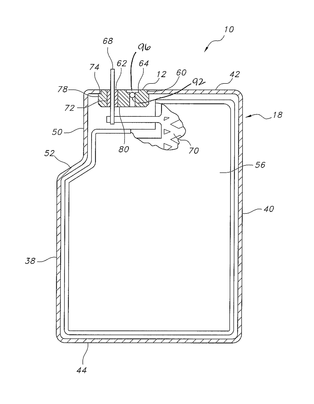
[0022]At the outset, it is understood that use of directional terms such as “upper” and “lower” is not intended to limit the scope of the present invention. Instead, those terms are used to describe the orientation depicted in the drawings, but that is not meant to limit an electrochemical cell incorporating an electrolyte fill port according to the present invention to the orientation that is shown.

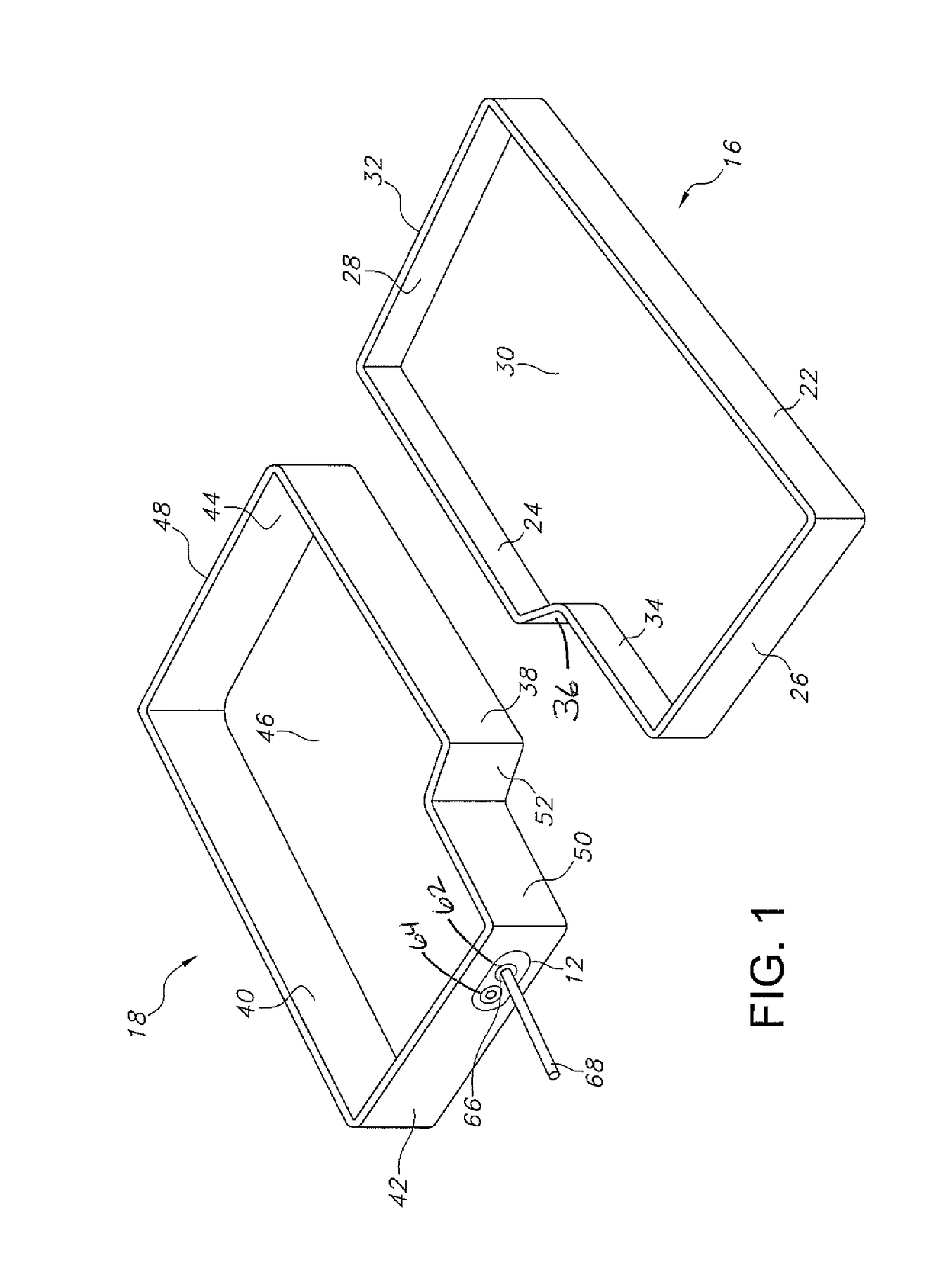
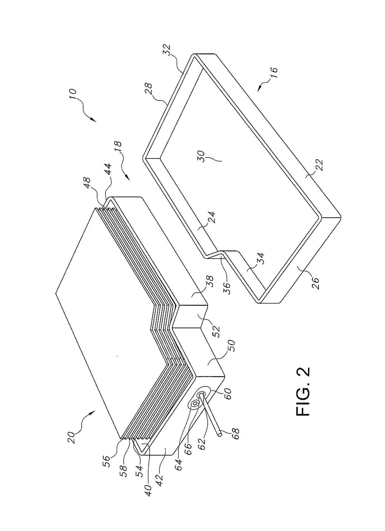
[0023]Turning now to the drawings, FIGS. 1 to 4 illustrate an exemplary electrochemical cell 10 according to the present invention. The exemplary electrochemical cell 10 comprises a header assembly 12 supported by a conductive metal casing 14, such as of stainless steel or titanium. In a preferred embodiment, the header 12 is manufactured by machining, powdered metallurgy, injection molding, or by stamping. The exemplary casing 14 comprises first and second mating clamshell portions 16 and 18. The mating clamshells 12 and 14 are stamped or otherwise formed from sheet metal.

[0024]First, d...


PUM


Abstract

A closure system for the electrolyte fill port of an electrochemical cell is described. A cell header has an electrolyte fill port comprising an upper opening sidewall extending from a header upper surface to an intermediate ledge located part-way through the header thickness. The ledge extends from a lower edge of the upper opening sidewall to an upper edge of a lower opening sidewall, the lower opening sidewall extending to the header lower surface. With respect to an axis of the electrolyte fill port, the upper opening sidewall has a first radius r1 and the lower opening sidewall has a second radius r2 at the ledge, the lower opening sidewall extending downwardly and inwardly along the axis from the second radius r2 to a third radius r3 at the header lower surface. The second radius r2 at the ledge is greater than the third radius r3 at the header lower surface. A closure system for an electrolyte fill port comprises a lower closure member secured to the lower opening sidewall by a lower weld; and an upper closure member secured to the upper opening sidewall by an upper weld. Importantly, the lower opening sidewall is provided with rifling.

Description

BACKGROUND OF THE INVENTION1. Field of the Invention[0001]The present invention relates to an improvement in the design of an electrochemical cell by enhancing hermeticity of the cell casing. In particular, the present invention is directed to a novel closure system for an electrolyte fill port. The closure system has first and second welded closure members with the first, lower closure member substantially sealing the fill port so that hermeticity of the second, upper closure member is enhanced.2. Prior Art[0002]In prior and current product lines, the design of a typical electrochemical cell includes a lid with separate ferrules or openings for a terminal pin feedthrough and an electrolyte fill port. Conventional designs consist of a lid or header supporting a glass-to-metal-seal (GTMS) for the terminal pin and a closure system for the electrolyte fill port. The battery electrodes are activated with electrolyte filled into the cell casing via the fill port. Then, the fill port is s...

Claims


Application Information

Patent Timeline
IPC IPC(8): H01M2/36H01M2/02H01M50/103H01M50/119H01M50/176H01M50/636
CPCH01M2/365H01M2/367H01M2/0285H01M2002/0297Y02E60/10H01M50/103H01M50/131H01M50/169H01M50/668H01M50/636H01M50/176H01M50/119
Inventor VOSS, GREGORY A.URSO, TINA L.TALAMINE, KENNETH B.
Owner WILSON GREATBATCH LTD
Why Eureka
Try Eureka