Method for manufacturing multilayer ceramic substrate
Inactive Publication Date: 2018-09-27
HITACHI METALS LTD
View PDF4 Cites 7 Cited by
Summary
Abstract
Description
Claims
Application Information
AI Technical Summary
This helps you quickly interpret patents by identifying the three key elements:
Problems solved by technology
Method used
Benefits of technology
Benefits of technology
The present invention provides a method for making a multi-layer ceramic substrate that is efficient and easy to extract the desired part. This method improves mass productivity of the substrate.
Problems solved by technology
However, as a result of a study by the present inventor, it was found that it may not be easy in some cases to form a cavity by the methods of Patent Document Nos. 1 and 2.
Method used
Image
Click on the blue label to locate the original text in one second.
Reading with bidirectional positioning of images and text.
[0111]A thermal expansion layer paste as prepared, and it was confirmed that the thermal expansion layer exhibited a thickness change sufficient for the formation of the cavity at a desired temperature. Ceramic green sheets were produced by forming a ceramic material including Al, Si and Sr as its main components and Ti, Bi, Cu, Mn, Na and K as its sub-components into a sheet shape.
[0112]Thermally-expansive microcapsules (F, FN series from Matsumoto Yushi-Seiyaku Co., Ltd.) having average particle sizes and expansion start temperatures shown in Table 1 were prepared as thermal expansion materials. TMC-108 (from Tanaka Kikinzoku Kogyo K.K.) was used as a vehicle, and the thermally-expansive microcapsules and the vehicle were mixed ether at weight ratio of 1:9 produce a paste. The obtained paste was applied on a PET film so that the thickness as dried is about 0.1 mm and then dried, thereby obtaining samples of thermal expansion layers. ...
example 2
[0115]Formation of Cavity
[0116]The amount of thickness change of the thermal expansion layer that is needed for forming a cavity without forming a groove was examined. Ceramic green sheets having a thickness of 110 μm were prepared, and six of them were layered together to form a ceramic green sheet laminate. The size of the cavity was 25 mm long, 25 mm wide and 0.1 mm deep. For the thermal expansion layer, the thermal expansion layer paste of Sample 1 described above was applied on a ceramic green sheet by using a screen printing method. The thickness of the thermal expansion layer was 0.01 mm, as measured by observing the cross section of the produced sheet laminate with a microscope. In order to vary the amount of thickness change, the heating temperature when expanding the thermal expansion layer was adjusted in accordance with FIG. 12. A plurality of samples were produced to evaluate the percentage with which the portion corresponding to the cavity was extracted properly. The r...
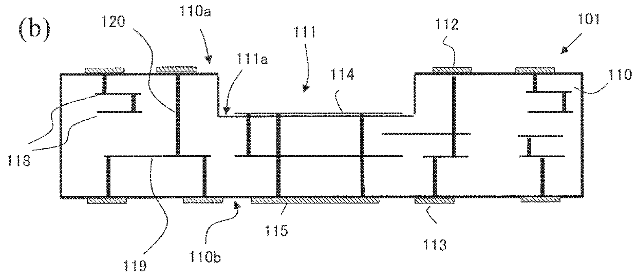
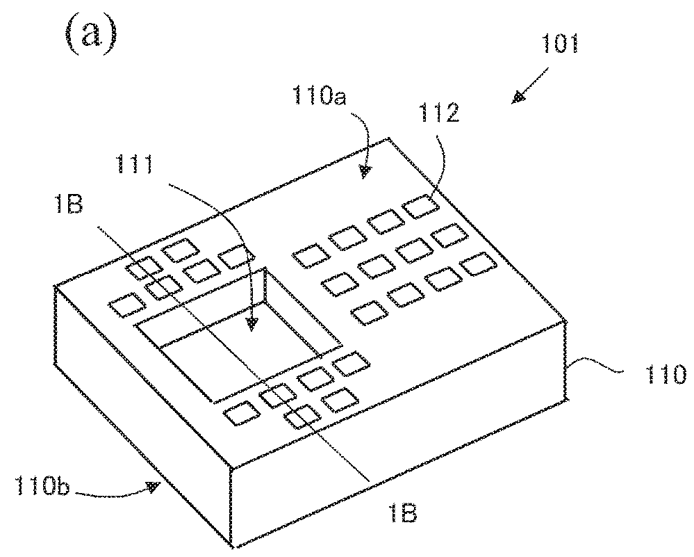
[0120]A multi-layer ceramic substrate was manufactured, in which a cavity was formed under the following condition.
[0121]First, a ceramic material including Al, Si and Sr as its main components and Ti, Bi, Cu, Mn, Na and K as its sub-components was prepared. A plurality of ceramic green sheets were obtained as described above using the ceramic material prepared.
[0122]Next, via holes were formed in the obtained ceramic green sheets by using a laser puncher, and screen printing was used to fill the via holes with a conductive paste and to form wiring patterns. A material including Ag as a conductive material was used as the conductive paste. Moreover, a thermal expansion layer was formed in a region of the first ceramic green sheet to be the bottom surface of the cavity. The thermal expansion layer was formed by a screen printing method using a thermal expansion layer paste so that the thickness as dried would be 10 μm. In the thermal e...
PUM
Property
Measurement
Unit
Time
aaaaa
aaaaa
Temperature
aaaaa
aaaaa
Temperature
aaaaa
aaaaa
Abstract
A method of producing a multi-layer ceramic substrate includes the steps of: (A) preparing a first ceramic green sheet with a thermal expansion layer arranged thereon, and at least one second ceramic green sheet with no thermal expansion layer arranged thereon; (B) laminating the first and second ceramic green sheets with the thermal expansion layer sandwiched therebetween, thereby obtaining a green sheet laminate; (C) pressure-bonding together the ceramic green sheets of the green sheet laminate; (D) heating and thereby expanding the thermal expansion layer in the pressure-bonded green sheet laminate; (E) extracting a portion of the green sheet laminate that has been displaced the expansion of the thermal expansion layer, thereby forming a cavity in the green sheet laminate; and (F) sintering the green sheet laminate with the cavity formed therein.
Description
TECHNICAL FIELD[0001]The present invention relates to a method of producing a multi-layer ceramic substrate having a cavity.BACKGROUND ART[0002]Multi-layer ceramic substrates have been widely used as wiring substrates for use in various electronic devices such as communication devices. Using a multi-layer ceramic substrate, it is possible to incorporate passive elements, such as capacitors, coils and transmission paths, into the substrate and implement electronic components on the surface of the substrate, thus realizing a small module. Moreover, in recent years, a cavity is provided in a multi-layer ceramic substrate and a semiconductor IC is accommodated in the cavity so as to achieve a low profile of the module as whole and to highly integrate and combine functions together.[0003]Such a multi-layer ceramic substrate with a cavity is commonly produced by laminating and pressure-bonding together a ceramic green sheet having an opening corresponding to the cavity and a ceramic green...
Claims
Application Information
Patent Timeline
Application Date:The date an application was filed.
Publication Date:The date a patent or application was officially published.
First Publication Date:The earliest publication date of a patent with the same application number.
Issue Date:Publication date of the patent grant document.
PCT Entry Date:The Entry date of PCT National Phase.
Estimated Expiry Date:The statutory expiry date of a patent right according to the Patent Law, and it is the longest term of protection that the patent right can achieve without the termination of the patent right due to other reasons(Term extension factor has been taken into account ).
Invalid Date:Actual expiry date is based on effective date or publication date of legal transaction data of invalid patent.

