Cylindrical contact-type microphone

a cylindrical contact and microphone technology, applied in the direction of microphone structure association, mouthpiece/microphone attachment, ceramic diaphragm, etc., can solve the problems of poor sound pick-up effect, inconvenient assembly, complex structure and large size of piezoelectric microphones, etc., to achieve convenient assembly, simple structure, and small size

Active Publication Date: 2018-09-27
HU QIANG
View PDF20 Cites 0 Cited by
  • Summary
  • Abstract
  • Description
  • Claims
  • Application Information

AI Technical Summary

Benefits of technology

[0004]In view of the above drawbacks existing in the prior art, the technical problem to be solved by the present invention is to provide a cylindrical contact-type microphone that is simple in structure, small in size and convenient in assembly, and may reduce production costs of enterprises.
[0013]The cylindrical contact-type microphone provided by the present invention employs a structure similar to that of an electret microphone, and the piezoelectric ceramic sheet is connected to the circuit board through the shell and the conductive polar ring. Consequently, the present microphone is featured by simple structure, small size and convenient assembly, the machining of which can be accomplished by means of production and machining devices and some accessories for electret microphones, thereby reducing production costs of enterprises.

Problems solved by technology

For such microphones, as sounds are converted into electric signals via electret diaphragms, sound pick-up effects are poor when environmental noises are loud.
However, existing piezoelectric microphones are complex in structure and large in size, which renders assembly inconvenient.
Moreover, as their machining manners are greatly different from those of traditional electret microphones, additional devices are required to be purchased for production and machining, which increases production costs of microphone manufacturing enterprises.

Method used


Image

  • Cylindrical contact-type microphone
  • Cylindrical contact-type microphone

Examples


Embodiment Construction

[0016]Embodiments of the present invention are further described below in detail in conjunction with the accompanying drawings, but they are not intended to limit the present invention. All of the similar structures employing the present invention, and similar variations thereof, shall be covered by the scope of protection of the present invention, and pause marks in the present invention all refer to coordinative relationships.

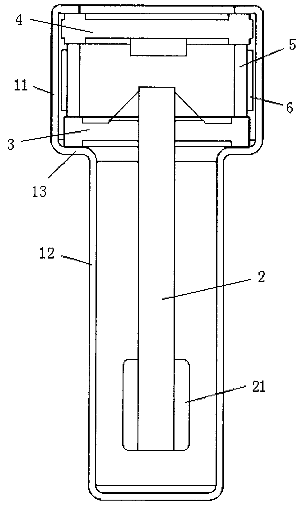
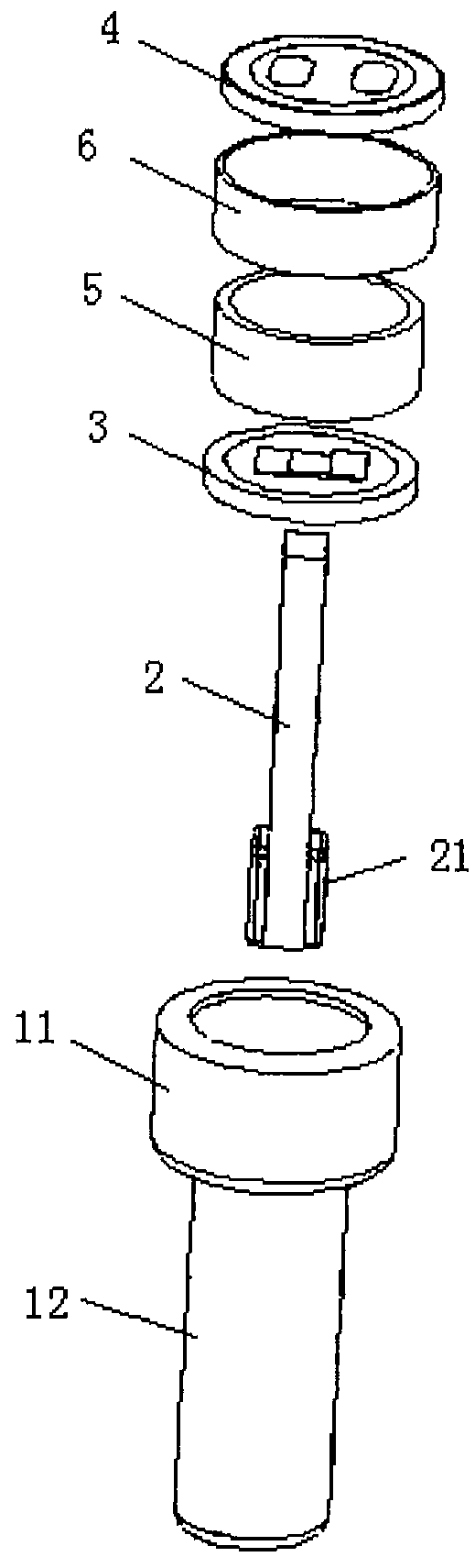
[0017]As shown in FIGS. 1-2, a cylindrical contact-type microphone provided by the embodiment of the present invention is characterized by comprising a shell and a circuit board 4 mounted within the shell, and it is further characterized by comprising a piezoelectric ceramic sheet 2;

[0018]the shell is a tapered, two-section cylindrical conductive cylinder body, a step 13 is formed at a joint portion of an upper cylinder section 11 and a lower cylinder section 12 of the shell, and a lower-stage connection, plate 3 and a conductive polar ring 5 are mounted with...


PUM


Abstract

A cylindrical contact-type microphone relates to the technical field of audio devices, and solves the technical problem of inconvenient assembly of an existing contact-type microphone. The microphone comprises a shell, and a circuit board (4), a piezoelectric ceramic sheet (2), a lower-stage connection plate (3) and a conductive polar ring (5) which are mounted within the shell, wherein the shell is a two-section cylindrical conductive cylinder body, and a negative signal lower connection sheet of the lower-stage connection plate (3) is electrically connected to a step (13) at a joint portion of an upper cylinder section (11) and a lower cylinder section (12) of the shell.

Description

FIELD OF THE INVENTION[0001]The present invention relates to the technology of audio devices, and more particularly, to the technology of a cylindrical contact-type microphone.BACKGROUND OF THE INVENTION[0002]Most of the traditional microphones are electret microphones. For such microphones, as sounds are converted into electric signals via electret diaphragms, sound pick-up effects are poor when environmental noises are loud.[0003]For piezoelectric microphones, as vibrations produced by sounds are converted into electric signals via piezoelectric ceramic sheets, sound pick-up effects are excellent in a noisy environment. However, existing piezoelectric microphones are complex in structure and large in size, which renders assembly inconvenient. Moreover, as their machining manners are greatly different from those of traditional electret microphones, additional devices are required to be purchased for production and machining, which increases production costs of microphone manufactur...

Claims


Application Information

Patent Timeline
Patent Type & Authority Applications(United States)
IPC IPC(8): H04R17/02H04R1/04H04R3/00H04R7/04H04R1/08
CPCH04R17/02H04R1/04H04R2307/023H04R1/021H04R1/08H04R3/00H04R2201/029H04R7/04
Inventor HU, QIANG
Owner HU QIANG
Why Eureka
Try Eureka