
Refrigeration cycle device and three-way flow rate control valve

Active Publication Date: 2018-10-18
SAMSUNG ELECTRONICS CO LTD
View PDF3 Cites 2 Cited by
  • Summary
  • Abstract
  • Description
  • Claims
  • Application Information

AI Technical Summary

Benefits of technology

The invention relates to a refrigeration system for cooling two storage compartments simultaneously. The technical effects of the invention include preventing excessive refrigerant consumption and ensuring optimal mixing of refrigerant between the two compartments. Additionally, the system is designed to prevent the interruption of the cooling effect due to temperature changes during the cooling process. The system achieves energy efficiency by controlling the flow rate of refrigerant to each compartment based on its unique temperature range. The invention is particularly useful in refrigeration units designed for use in vehicles.

Problems solved by technology

When, in a state in which two storage compartments are being cooled, cooling of one of the storage compartments is suppressed, an effect of a mixer cannot be maintained when a refrigerant mixed in the mixer is not circulated at all to a cooler configured to cool at least the one of the storage compartments, and the amount of refrigerant becomes excessive when all of the refrigerant is circulated to a cooler configured to cool at least the other storage compartment.
As a result, energy efficiency cannot be achieved.

Method used


Image

  • Refrigeration cycle device and three-way flow rate control valve
  • Refrigeration cycle device and three-way flow rate control valve
  • Refrigeration cycle device and three-way flow rate control valve

Examples


Embodiment Construction

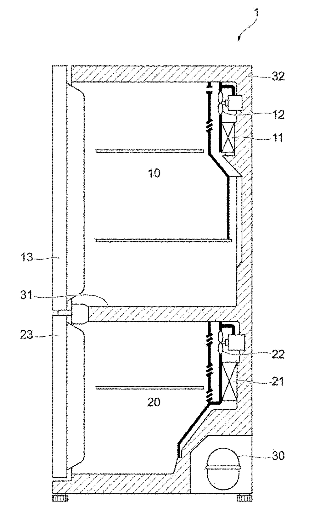
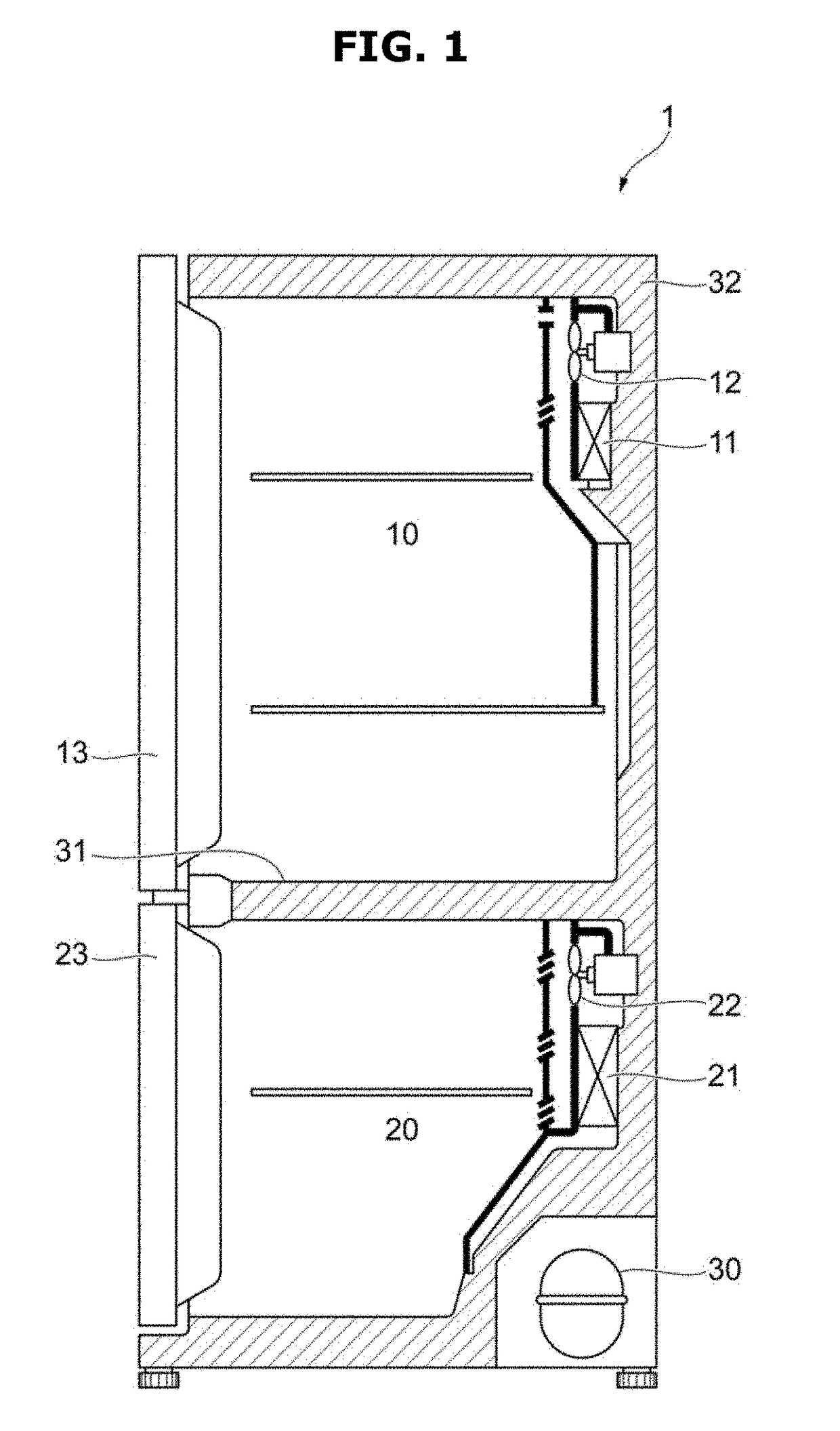
[0076]FIGS. 1 through 27, discussed below, and the various embodiments used to describe the principles of the present disclosure in this patent document are by way of illustration only and should not be construed in any way to limit the scope of the disclosure. Those skilled in the art will understand that the principles of the present disclosure may be implemented in any suitably arranged system or device.

[0077]Like reference numerals refer to like elements throughout. Not all parts of embodiments are described herein, and general content in the art to which the present disclosure pertains or overlapping content between the embodiments will be omitted. The terms “part, module, member, and block” used herein may be implemented with software or hardware, and depending on the embodiment, a plurality of “parts, modules, members, and blocks” may be implemented with a single element, or a single “part, module, member, or block” may include a plurality of elements.

[0078]Throughout the spe...


PUM


Abstract

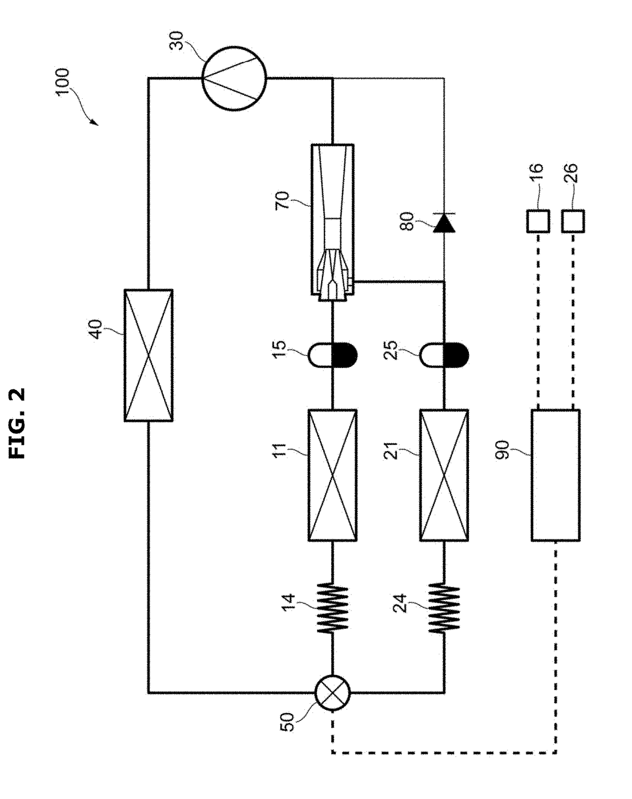
Disclosed herein are a refrigeration cycle device and three-way flow rate control valve. In a refrigeration cycle device including a compressor, first and second coolers configured to cool first and second storage compartments at least, respectively, and a mixer configured to mix refrigerants that have passed through the first and second coolers, a refrigerant flow path is switched so that refrigerants of first and second flow rates are circulated to the first and second coolers, respectively, while the first and second storage compartments are being cooled, and a refrigerant flow path is switched so that a refrigerant of a specific flow rate, which is smaller than a first flow rate but is not zero, is circulated to the first cooler after cooling of the first storage compartment is completed.

Description

CROSS-REFERENCE TO RELATED APPLICATION(S) AND CLAIM OF PRIORITY[0001]This application is based on and claims priority under 35 U.S.C. § 119 to Japanese Patent Application Nos. 2017-081566 filed on Apr. 17, 2017, 2017-214014 filed on Nov. 6, 2017, and 2018-024893 filed on Feb. 15, 2018, in the Japan Patent Office and Korean Patent Application No. 10-2018-0034200 filed on Mar. 26, 2018 in the Korean Intellectual Property Office, the disclosures of which are incorporated herein by reference in their entireties.BACKGROUND1. Field[0002]Embodiments of the present disclosure relate to a refrigeration cycle device and three-way flow rate control valve.2. Description of the Related Art[0003]There is known a refrigeration cycle device including a first cooling space, a second cooling space at a lower temperature than the first cooling space, a compressor, a condenser, a high-temperature-side switcher connected to the condenser, first and second expansion devices arranged in parallel through t...

Claims


Application Information

Patent Timeline
IPC IPC(8): F16K31/04F16K11/048F25B41/06F25B5/02F25D13/04
CPCF16K11/048F25B41/067F25B2309/004F16K31/047F25B2600/2511F25B5/02F25D13/04F16K31/535F16K11/074F25B41/00F25D11/022F16K31/041F25B2341/0011F25B49/02F25B2700/2117F25D2700/12F25D2700/122
Inventor MATSUZAKI, TAKASHIKOBAYASHI, MAKOTOSHIMIZU, KAZUOSHIMIZU, TATSUYASUZUKI, TOSHIAKI
Owner SAMSUNG ELECTRONICS CO LTD
Learn More