

Plasma Separation Membrane
a technology of separation membrane and plasma, which is applied in the field of plasma separation membrane, can solve the problems of impurities of cells or cell debris
- Summary
- Abstract
- Description
- Claims
- Application Information
AI Technical Summary
Benefits of technology
Problems solved by technology
Method used
Image

Examples
example 1
[0090]A polymer solution was prepared by dissolving 18.0 wt-% polyethersulfone (PES; BASF Ultrason 6020), 3.25 wt-% low molecular weight polyvinylpyrrolidone (PVP; BASF K30) and 8.0 wt-% high molecular weight polyvinylpyrrolidone (PVP; BASF K85 or K90) and 6.0 wt-% water in 70.75 wt-% N-methylpyrrolidone (NMP). The viscosity of the polymer solution at room temperature was 61810 mPa×s.
[0091]To prepare the solution, NMP and the water were placed in a three neck-flask with finger-paddle agitator in the centre neck. Then, the PVP was added to the NMP and stirred at 50° C. until a homogeneous clear solution was formed. Finally, the polyethersulfone (PES) was added. The mixture was stirred at 50° C. until a clear high viscous solution is obtained. The warm solution was cooled down to 20° C. and degassed. To fully degas the solution the highly viscous polymer solution was transferred into a stable stainless steel container, the container was closed tightly and vacuum was applied to the con...
example 2
[0095]In Example 2 the same compositions of the polymer solution and the precipitation bath were used as in Example 1. The viscosity of the polymer solution at room temperature was 62500 mPa×s. As centre fluid a mixture of 20.0 wt.-% water and 80.0 wt.-% NMP was used. The membrane formation procedure was the same as in Example 1 with the exceptions that the temperature of the die was 50° C., distance between the die and the precipitation bath was 4 cm, and the temperature of the precipitation bath was 50° C.
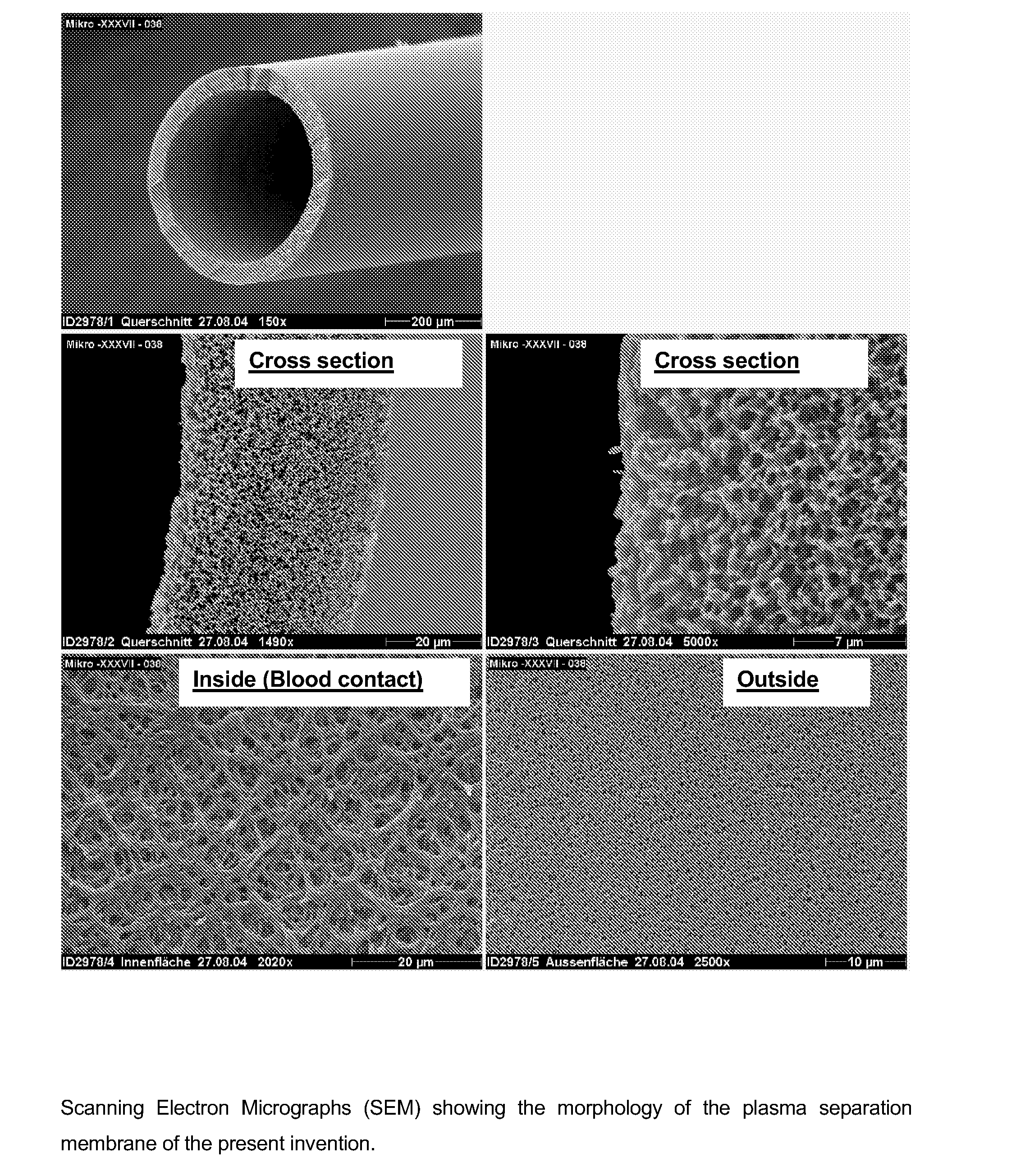
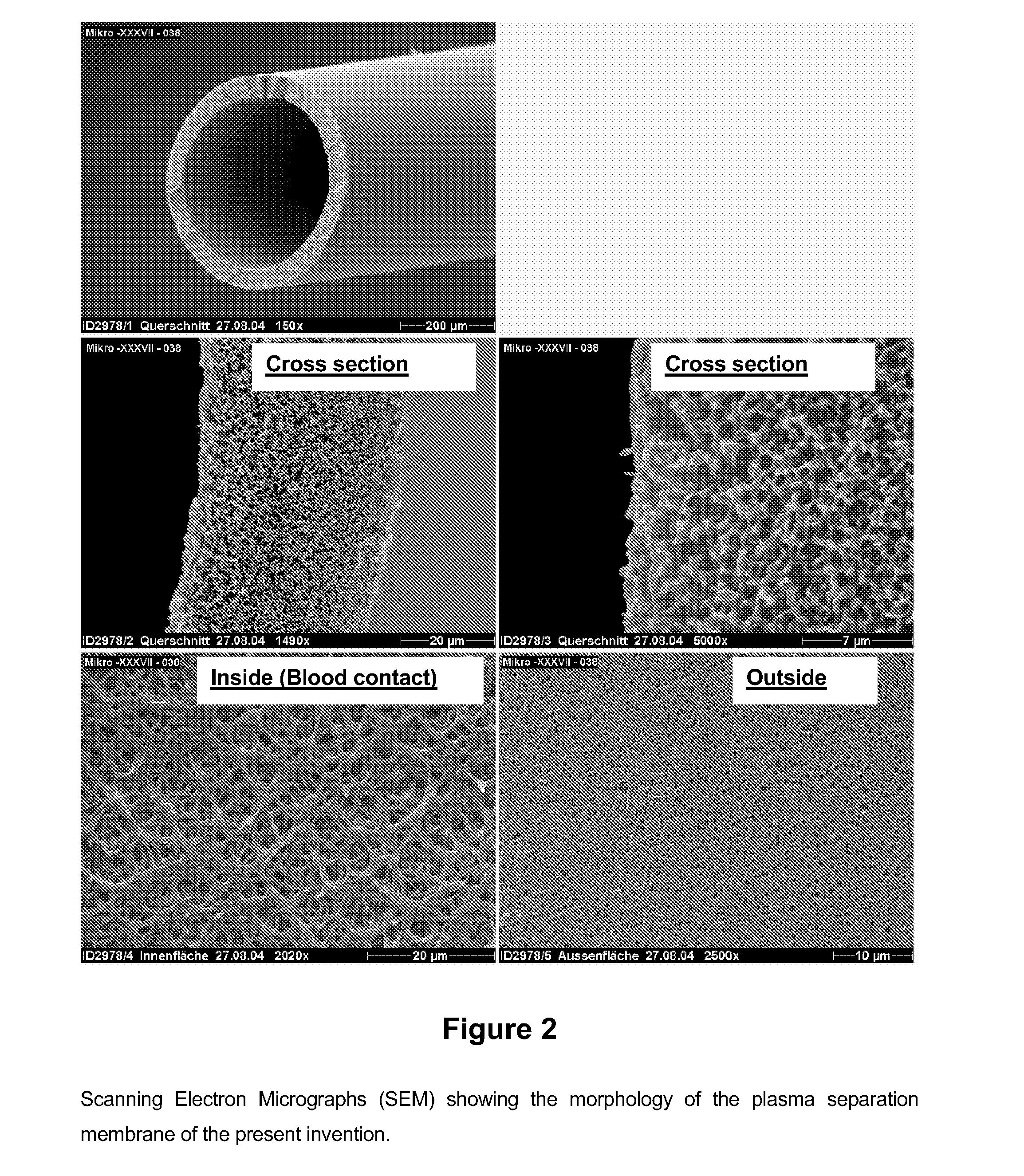
[0096]The resulting hollow fibre membrane had an inner diameter of 320 μm, an outer diameter of 420 μm and a fully asymmetric membrane structure. The total protein sieving coefficient was 100% at a transmembrane pressure (TMP) of 50 mmHg (Mean Blood flow QB: 3.1 ml / min, mean shear rate: 255 1 / s). The degree of free haemoglobin as the corrected filtrate value was below the border of starting haemolysis of 0.2 for the tested value of 50 mmHg.
[0097]A scanning electron micrograph of ...
example 3
[0098]In Example 3 the same compositions of the polymer solution and the precipitation bath were used as in Example 1. The viscosity of the polymer solution at room temperature was 62500 mPa×s. As centre fluid a mixture of 22.0 wt.-% water and 78.0 wt.-% NMP was used. The membrane formation procedure was the same as in Example 1 with the exceptions that the temperature of the die was 50° C., distance between the die and the precipitation bath was 8 cm, and the temperature of the precipitation bath was 50° C. Further, in addition to examples 1 and 2 the liquid fibre leaving the spinning die passed a spinning shaft of 6 cm length extending from the exit of the die to a distance of about 2 cm above the surface of the precipitation bath. The spinning shaft provided for a space of a conditioned atmosphere of steam or humid air surrounding the fibre when travelling from the exit of the spinning die into the precipitation bath. The steam or humid air was thereby generated by evaporation of...
PUM
| Property | Measurement | Unit |
|---|---|---|
| Temperature | aaaaa | aaaaa |
| Temperature | aaaaa | aaaaa |
| Temperature | aaaaa | aaaaa |
Abstract
Description
Claims
Application Information