
Compact multi-color flow cytometer having compact detection module

a detection module and multi-color technology, applied in the field of detection modules of flow cytometers, can solve the problems of signal crosstalk between detectors, dye emission spectrum overlap, expedient but costly way to increase the number of fluorochromes that can be simultaneously detected, etc., and achieve the effect of low cos

Active Publication Date: 2018-10-18
CYTEK BIOSCI
View PDF5 Cites 7 Cited by
  • Summary
  • Abstract
  • Description
  • Claims
  • Application Information

AI Technical Summary

Benefits of technology

The invention has different versions that are described in the claims. The technical effect of these versions is to improve the performance and efficiency of the invention in a specific task.

Problems solved by technology

However, emission spectrum can overlap between dyes.
Increasing the number of lasers provides an expedient but costly way to increase the number of fluorochromes that can be simultaneously detected.
This can lead to signal crosstalk between detectors for the different lasers.
However, this resulted in a larger diameter light beam that limited the number of detectors, such as to six detectors, depending on the size of the final image required.
However, the number of detectors is limited by the aberration introduced by reflections from the spherical micro-mirrors.
Since the image size increases along the detector chain, to increase the number of detector channels down the row in the detector chain, large area detectors are required resulting in a large flow cytometer that is bulky and expensive.
However, this approach to increasing the number of detectable fluorochromes has two major limitations.
The continuous, linear characteristics of a dispersion-element / detector array does not allow for bandwidths to be adjusted to take advantage of the true nature of fluorochrome spectra.
Additionally, scattered light from other lasers, if present, is unavoidably collected by the array of detectors.
This scattered light compromises the fluorescence signal that is to be detected by a detector.

Method used


Image

  • Compact multi-color flow cytometer having compact detection module
  • Compact multi-color flow cytometer having compact detection module
  • Compact multi-color flow cytometer having compact detection module

Examples


Embodiment Construction

[0034]In the following detailed description of the embodiments, numerous specific details are set forth in order to provide a thorough understanding. However, it will be obvious to one skilled in the art that the embodiments can be practiced without these specific details. In other instances well known methods, procedures, components, and circuits have not been described in detail so as not to unnecessarily obscure aspects of the embodiments of the invention.

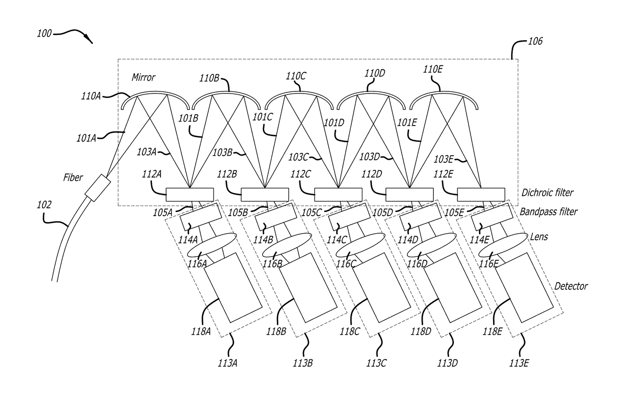
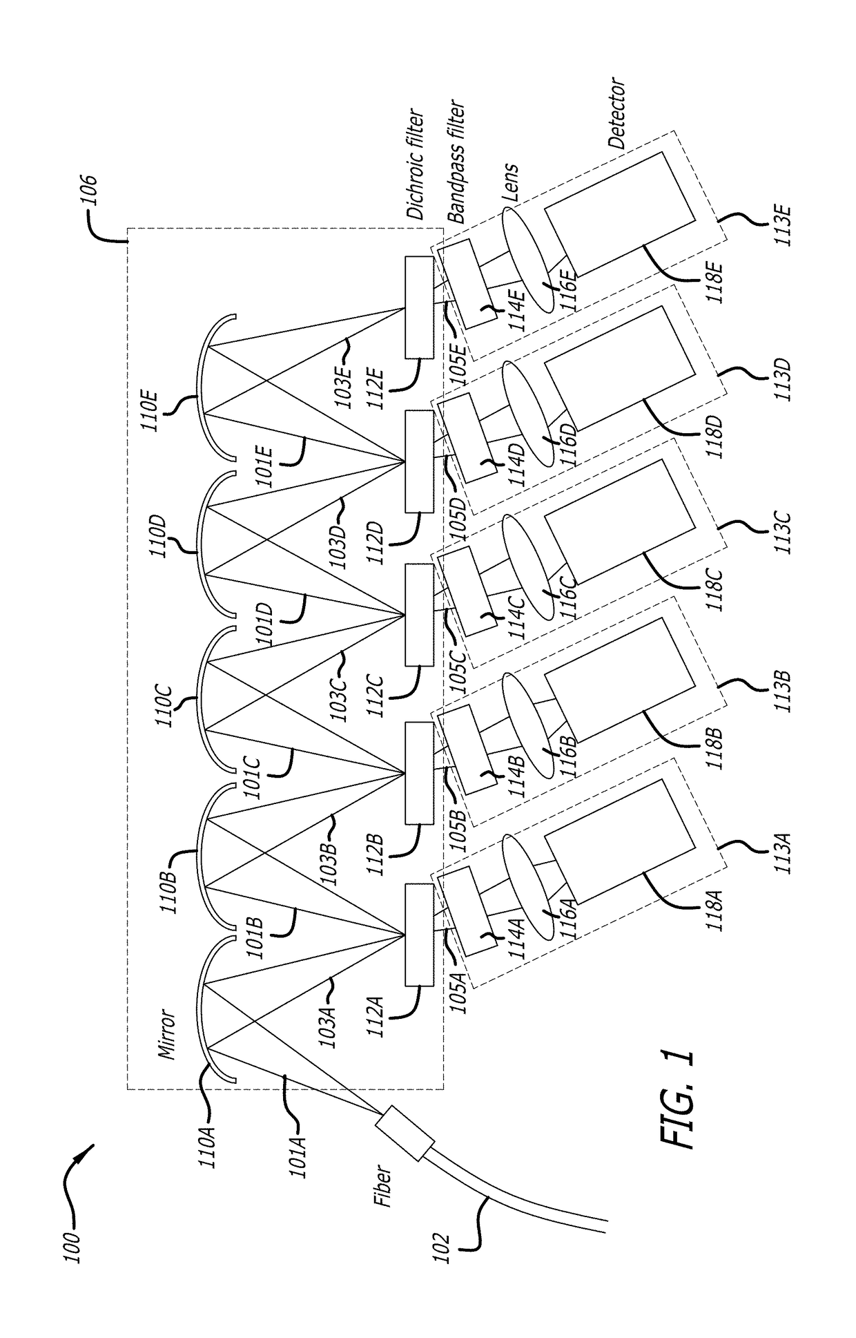
[0035]The embodiments of the invention include a method, apparatus and system for a flow cytometer with a compact highly multiplexed detection module.

GENERAL OVERVIEW

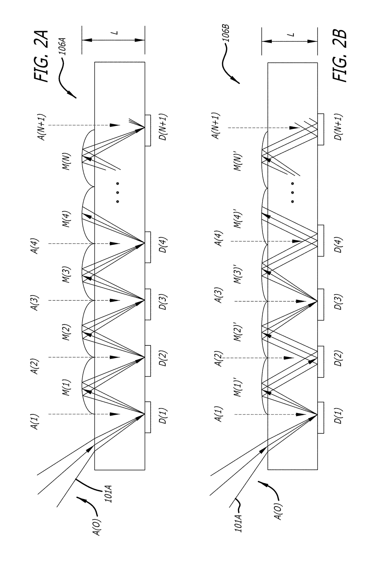
[0036]A flow cytometer with a compact detection module for fluorescence is disclosed with an increased number of detectors and a minimal image size at the detectors compared to prior flow cytometers. Each detector module is fed by at least one laser. Multiple lasers can be supported by multiple detector arrays in a compact manner. The increased number of detectors i...


PUM

PropertyMeasurementUnit
wavelengthsaaaaaaaaaa

Abstract

A system, an apparatus, and a method are provided for a modular flow cytometer with a compact size. In one embodiment, the modular flow cytometry system includes the following: a laser system for emitting laser beams; a flow cell assembly positioned to receive the laser beams at an interrogation region of a fluidics stream where fluoresced cells scatter the laser beams into fluorescent light; a fiber assembly positioned to collect the fluorescent light; and a compact light detection module including a first image array having a transparent block, a plurality of micro-mirrors in a row coupled to a first side of the transparent block, and a plurality of filters in a row coupled to a second side of the transparent block opposite the first side.

Description

CROSS REFERENCE TO RELATED APPLICATION[0001]This patent application is a continuation in part application claiming priority to U.S. patent application Ser. No. 15 / 498,397 titled COMPACT MULTI-COLOR FLOW CYTOMETER filed on Apr. 26, 2017 by inventors David Vrane et al. incorporated herein by reference for all intents and purposes. Application Ser. No. 15 / 498,397 claims the benefit of U.S. Provisional Patent Application No. 62 / 237,946 titled COMPACT MULTI-COLOR FLOW CYTOMETER filed on Apr. 26, 2016 by inventors David Vrane et al., incorporated herein by reference for all intents and purposes.[0002]This patent application is also a continuation in part application claiming priority to U.S. patent application Ser. No. 15 / 659,610 titled COMPACT DETECTION MODULE FOR FLOW CYTOMETERS filed on Jul. 25, 2017 by inventors Ming Yan et al., incorporated herein by reference for all intents and purposes. Application Ser. No. 15 / 659,610 claims the benefit of U.S. Provisional Patent Application No. 6...

Claims


Application Information

Patent Timeline
Patent Type & Authority Applications(United States)
IPC IPC(8): G01N15/14G01N21/53G01N21/64G01J3/44G01J3/14G01J3/18
CPCG01N15/1436G01N15/1459G01N21/53G01N21/6486G01J3/4406G01J3/14G01J3/18G01N2015/0065G01N2015/1006G01N2021/6421G01N2201/06113G01J2003/1213G01J3/36G01J3/021G01J3/0218G01J3/0291G01N15/1434G01N2021/6471G01J3/0202G01J3/0208G01J3/0256G01J3/2803G01N15/01
Inventor YAN, MINGHSIEH, YUNG-CHIEHVRANE, DAVIDCHASE, ERICJIANG, WENBIN
Owner CYTEK BIOSCI
Learn More