Atrio-Ventricular Valve Stent with Native Leaflet Grasping and Holding Mechanism

a native leaflet and stent technology, applied in the field of heart valve stents, can solve the problems of high morbidity and mortality, high risk of complication in high risk of surgery in patients with damaged cardiac function, so as to prevent any traumatic damage of leaflet tissue, increase the anchoring of the stent, and prevent damage to cardiac tissu

Active Publication Date: 2018-10-25
EPYGON
View PDF3 Cites 22 Cited by
  • Summary
  • Abstract
  • Description
  • Claims
  • Application Information

AI Technical Summary

Benefits of technology

[0033]To prevent any traumatic damage of leaflet(s) tissue, sleeves can be used to cover the engagement member(s). For the same purpose to prevent damages to the cardiac tissue the distal end of the engagement members can be protected by protection caps.
[0034]In some embodiments in addition to the engagement member(s) and with the objective to further increase the anchoring of the stent, at least two or more extension bodies fixed to the stent annular zone, i.e. not to the bottom of the ventricular part of the stent are placed below the mitral annulus to secure the stent

Problems solved by technology

It is well known that open-heart mitral valve surgery induces a high risk of morbidity and mortality, one of the main reasons is that mitral valve disease may be the cause or the consequence of left ventricular failure and surgery in patients with damaged cardiac function carries high mortality.
However, there are three major disadvantages using this approach; (i) it is well known that the left atrium is associated with thromboembolic events especially in patients with mitral disease and atrial fibrillation, it sounds logical that the large atrial protrusion of this type of valve may increase the risk of this complication; (ii) low profile ventricular valves are often associated with high-risk perivalvular leakage due to the limited area of attachment between the valve stent and the annular/ventricular tissue and (iii) the presence of chronic inflammation due to the hooks' tissue penetration that can facilitate secondary infection (endocarditis).
When transcatheter mitral valve prosthesis is used to replace the native valve, resection is not feasible a

Method used


Image

  • Atrio-Ventricular Valve Stent with Native Leaflet Grasping and Holding Mechanism
  • Atrio-Ventricular Valve Stent with Native Leaflet Grasping and Holding Mechanism
  • Atrio-Ventricular Valve Stent with Native Leaflet Grasping and Holding Mechanism

Examples


Embodiment Construction

[0039]The invention is discussed below in a more detailed way with examples illustrated by the following figures:

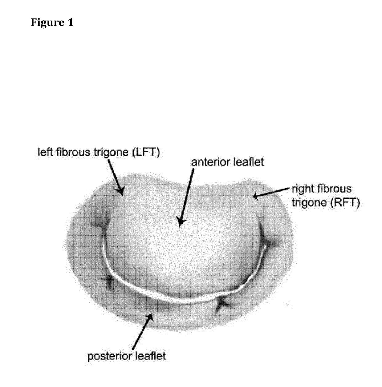
[0040]FIG. 1 represents a native mitral valve.

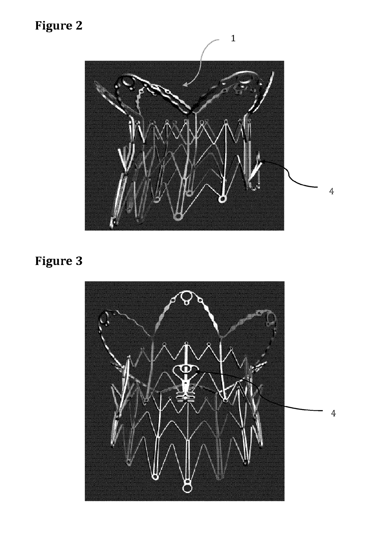
[0041]FIG. 2 shows an example of a mitral valve stent according to the invention.

[0042]FIG. 3 better shows the anterior side of the stent of FIG. 2.

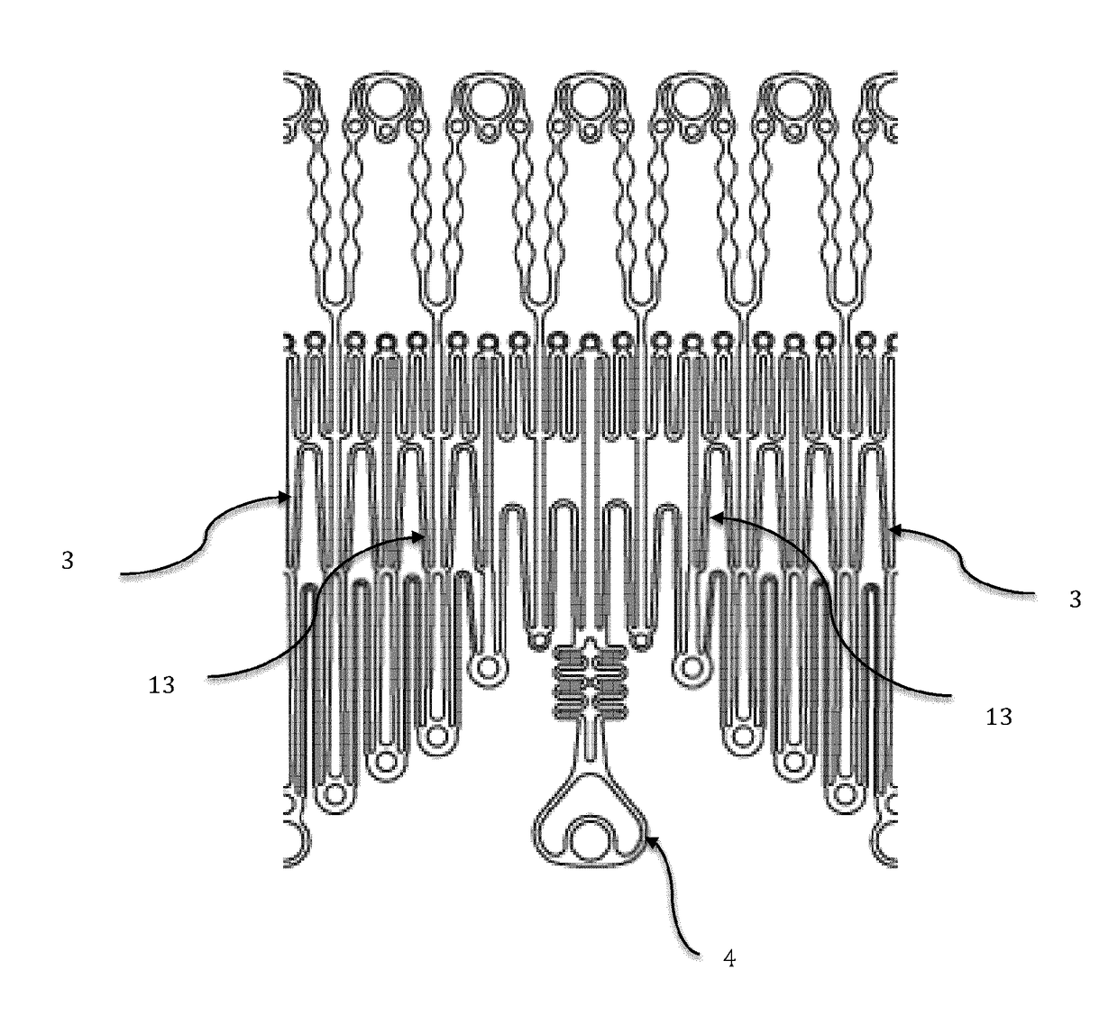
[0043]FIG. 4 shows a portion of a stent according to the invention, in a flat configuration.

[0044]FIG. 5 represents native leaflet retained by a stent according to the invention.

[0045]FIG. 6 represents the leaflet of FIG. 5 in a locked position.

[0046]FIG. 7 shows different orientations of an engagement member according to the invention.

[0047]FIG. 8 illustrates another example showing the fixation of an engagement member to the stent body.

[0048]FIG. 9 shows a stent according to the invention in a collapsed state with only one anterior engagement member.

[0049]FIG. 10 shows a stent according to the invention in a collapsed state with both one anterior and one posterior engagement memb...


PUM


Abstract

Atrio-ventricular valve stent (1) having a tubular shape, with a sub annular anterior side (2), a sub annular posterior side (3) and sub annular lateral sides (13), the sub annular anterior side (2) comprising a self-folding native leaflet engagement member (4-9) that forms a straight extension of said sub annular anterior side (2) when the stent (1) is collapsed and that is folded on itself when the stent (1) is in an expanded state; said engagement member (4-9) forming an integral part of the stent (1) and wherein each sub annular lateral side (13) is longer than said sub annular anterior side (2) when the stent (1) is in an expanded state.

Description

FIELD OF INVENTION[0001]The present invention refers to heart valve stents, in particular atrio-ventricular valve stents that comprise a native leaflet locking mechanism and / or an anchoring system to the cardiac tissue.STATE OF THE ART[0002]Mitral valve (see FIG. 1) is not only a valve but also a part of the left ventricle. The mitral apparatus includes the papillary muscles, the tendinous chordae, the two leaflets and the mitral annulus, which altogether work as a valve. Anatomically, the anterior segment of the mitral annulus between the two commissures or the two trigones (⅓ of the mitral annulus length) doesn't move. The posterior segment of the mitral annulus (⅔ of the mitral annulus length), on the contrary, moves accordingly to the left ventricle contraction.[0003]It is well known that open-heart mitral valve surgery induces a high risk of morbidity and mortality, one of the main reasons is that mitral valve disease may be the cause or the consequence of left ventricular fail...

Claims


Application Information

Patent Timeline
IPC IPC(8): A61F2/24
CPCA61F2/2448A61F2/2418A61F2210/0014A61F2220/0016A61F2230/0034A61B17/064A61F2/243A61F2/2466
Inventor PASQUINO, ENRICOSCORSIN, MARCIOPASQUINO, STEFANOMARCHISIO, ANDREAVALERIO, LORENZOCASALEGNO, SERGIOGARD, MARCOARRU, PIETRO
Owner EPYGON
Why Eureka
Try Eureka