X-ray phase contrast imaging system

a contrast imaging and phase contrast technology, applied in the field of x-ray phase contrast imaging system, can solve the problems of generating unintended moire fringe, self-image cannot be detected by a general-purpose detector, and generating artifacts (virtual images) in the captured image, so as to eliminate the noise of the fourier transform image

Active Publication Date: 2018-10-25
SHIMADZU CORP
View PDF3 Cites 26 Cited by
  • Summary
  • Abstract
  • Description
  • Claims
  • Application Information

AI Technical Summary

Benefits of technology

[0013]According to the present invention, since the aforementioned grating positional displacement acquisition section acquires the positional displacement of the grating based on the Fourier transform image, the position adjustment of the grating can be performed based on the obtained positional displacement of the grating. Therefore, it is possible to adjust the positional displacement of the grating without depending on knowledge and / or experience of a measurer and shorten the adjustment time.
[0038]By using such a Fourier transform reference image, when eliminating the noise of the Fourier transform image, the first-order peak of the Fourier transform image can be suppressed from being eliminated together with the noise by the first-order peak of the Fourier transform reference image. As a result, the noise of the Fourier transform image can be eliminated regardless of the position of the first-order peak in the Fourier transform image.

Problems solved by technology

The period of the self-image of the formed phase grating is so small that the self-image cannot be detected by a general-purpose detector.
However, in the Talbot Lau interferometer described in WO 2014 / 030115, when the relative position between the phase grating and the absorption grating is displaced from the design position, an unintended moire fringe is generated.
In this case, since the unintended moire fringe is detected by the detector, there is a disadvantage that an artifact (virtual image) is generated in the captured image due to the unintended moire fringe.
For this reason, there are problems that the measurer is required to have knowledge and / or experience and it takes time to adjust the grating positioning.

Method used


Image

  • X-ray phase contrast imaging system
  • X-ray phase contrast imaging system
  • X-ray phase contrast imaging system

Examples


first embodiment

[0063]With reference to FIG. 1 to FIG. 16, a configuration of an X-ray phase contrast imaging system 100 according to a first embodiment of the present invention will be described.

(Configuration of X-Ray Phase Contrast Imaging System)

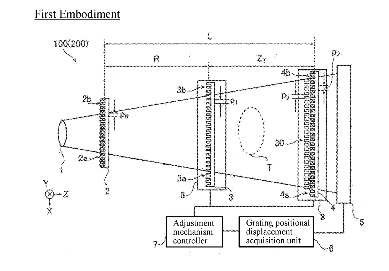
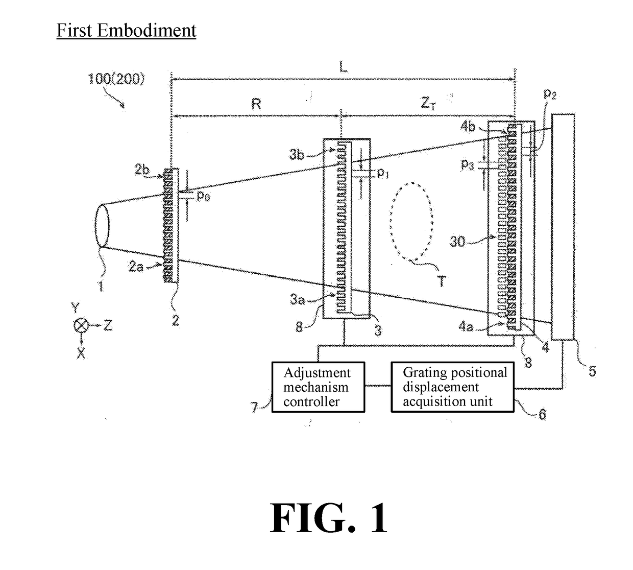
[0064]As shown in FIG. 1, the X-ray phase contrast imaging system 100 is an apparatus for imaging the inside of the object T by using the phase contrast of the X-ray that has passed through the object T. Further, the X-ray phase contrast imaging system 100 is an apparatus for imaging the inside of the object T utilizing a Talbot effect. For example, in nondestructive inspection applications, the X-ray phase contrast imaging system 100 can be used for imaging an inside of an object T as an object. Further, in medical applications, for example, the X-ray phase contrast imaging system 100 can be used for imaging an inside of an object T as a living body.

[0065]FIG. 1 is a top view of the X-ray phase contrast imaging system 100. As shown in FIG. 1, the X-ray...

second embodiment

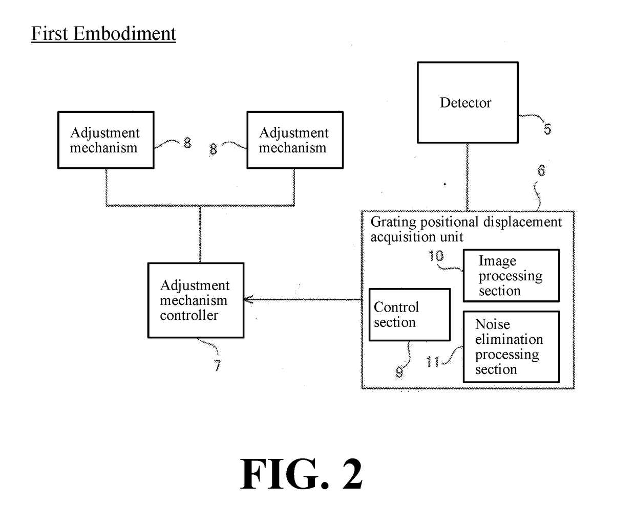
[0182]Next, with reference to FIG. 1, FIG. 2, FIG. 17 to FIG. 20, the X-ray phase contrast imaging system 200 (see FIG. 1) according to a first embodiment of the present invention will be described. Unlike the first embodiment in which the frequency noise is eliminated before performing the Fourier transform on the interference fringe image 13, in the second embodiment, the image processing section 10 (see FIG. 2) is configured to eliminate the noise 22 (see FIG. 18) generated in the Fourier transform image 14 using the Fourier transform reference image 23 (see FIG. 19) previously obtained by Fourier transforming the interference fringe image 13.

[0183]Note that the same reference numerals are allotted to the same configurations as those of the first embodiment, and the description thereof will be omitted.

[0184]Here, in the case where a pixel defect occurs in the detector 5 or a defect occurs in the first grating 3 and / or the second grating 4, as shown in FIG. 17, in the interference...


PUM

PropertyMeasurementUnit
positional displacementaaaaaaaaaa
displacementaaaaaaaaaa
positional displacementaaaaaaaaaa

Abstract

An X-ray phase contrast imaging system includes an X-ray source, a detector, a plurality of gratings including a first grating and a second grating, and a grating positional displacement acquisition section configured to obtain a positional displacement of the grating based on a Fourier transform image obtained by Fourier transforming an interference fringe image detected by the detector.

Description

CROSS-REFERENCE TO RELATED APPLICATIONS[0001]The priority application number JP2017-084030, entitled “X-ray phase contrast imaging system”, filed on Apr. 20, 2017, invented by Naoki Morimoto, Taro Shirai, Takahiro Doki, Satoshi Sano, and Akira Horiba, and JP2018-035646, entitled “X-ray phase contrast imaging system”, filed on Feb. 28, 2018, invented by Naoki Morimoto, Taro Shirai, Takahiro Doki, Satoshi Sano, and Akira Horiba, upon which this patent application is based are hereby incorporated by reference.BACKGROUND OF THE INVENTIONField of the Invention[0002]The present invention relates to an X-ray phase contrast imaging system.Description of the Background Art[0003]Conventionally, an X-ray phase contrast imaging system is known. Such an X-ray phase contrast imaging system is disclosed in, for example, WO 2014 / 030115.[0004]WO 2014 / 030115 discloses an X-ray phase contrast imaging system for imaging a phase contrast image by detecting a moire fringe generated by translating a sourc...

Claims


Application Information

Patent Timeline
Patent Type & Authority Applications(United States)
IPC IPC(8): G01N23/041
CPCG01N23/041G01N2223/401G01N2223/1016A61B6/06A61B6/52A61B6/5205A61B6/5258A61B6/4035A61B6/4291A61B6/484A61B6/5211A61B6/5264A61B6/547A61B6/584G01N23/20075G16H50/20G01N2223/313G01N2223/064G01N2223/302G01N2223/32G01N23/20008G01N2021/4186G01T1/2914G06T2207/20056G06T7/262G21K1/06G21K2207/005
Inventor MORIMOTO, NAOKISHIRAI, TARODOKI, TAKAHIROSANO, SATOSHIHORIBA, AKIRA
Owner SHIMADZU CORP
Why Eureka
Try Eureka