Method of Assembling Turbine, Assembly Work Supporting System, and Control Program

a technology of supporting system and turbine, which is applied in the direction of computer control, program control, instruments, etc., can solve the problems of affecting the operation period of periodical turbine inspection, pressing on the other, and the upper half of the casing fastening together is very large, so as to shorten the assembly period and maintain the accuracy of the positional adjustment of the stationary par

Active Publication Date: 2018-10-25
MITSUBISHI POWER LTD
View PDF4 Cites 4 Cited by
  • Summary
  • Abstract
  • Description
  • Claims
  • Application Information

AI Technical Summary

Benefits of technology

[0008]According to the present invention, it is possible to provide a method of assembling a turbine, an assembly work supporting system, and a control program making it possible to maintain accuracy in the positional adjustment of the stationary part while shortening the turbine assembly period through omission of temporary assembly of the casing.

Problems solved by technology

In addition, the bolts fastening together the casing upper half part and the casing lower half part are very large and rather hard to cool.
Thus, in the methods of Patent Documents 1 and 2, it is necessary to secure a very long period of time for the temporary assembly of the casing, which greatly affects the operation period of the periodical turbine inspection or the like.
Further, in a case where the operation period is previously determined, it can be a cause to press upon the other steps.
In addition, in the methods of Patent Documents 1 and 2, due to the difference in the skill level of the measurement workers, there is involved variation in the accuracy in the measurement of the moving amount of the stationary part, so that there is the possibility of deterioration in the positional adjustment accuracy for the stationary part.
Further, it is hard to apply the methods to a turbine which cannot be entered by the measurement worker as in the case of a small turbine.

Method used


Image

  • Method of Assembling Turbine, Assembly Work Supporting System, and Control Program
  • Method of Assembling Turbine, Assembly Work Supporting System, and Control Program
  • Method of Assembling Turbine, Assembly Work Supporting System, and Control Program

Examples


first embodiment

(Construction)

1. Turbine

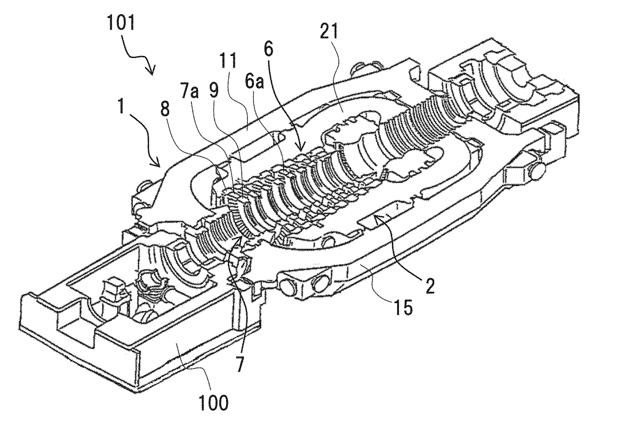
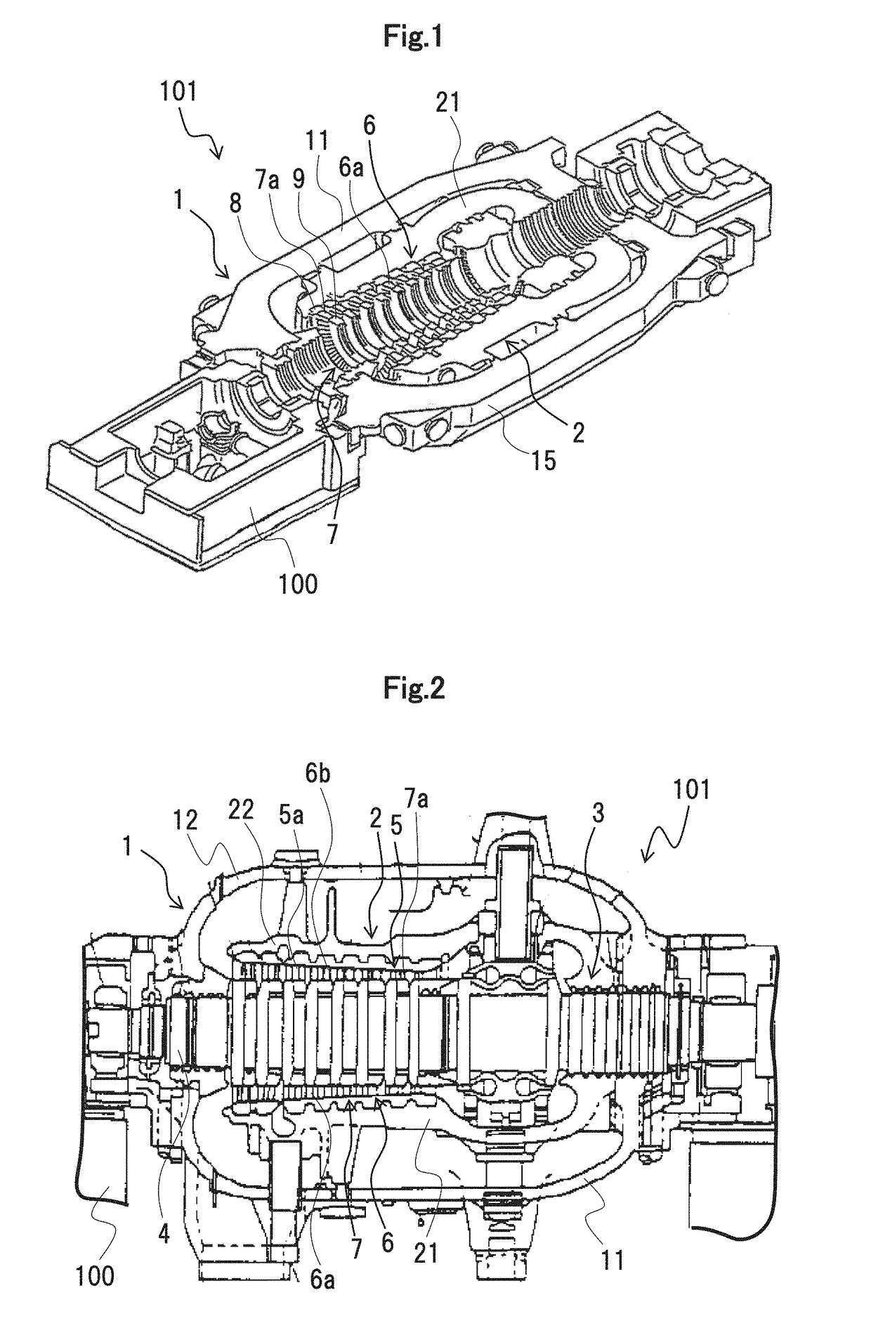
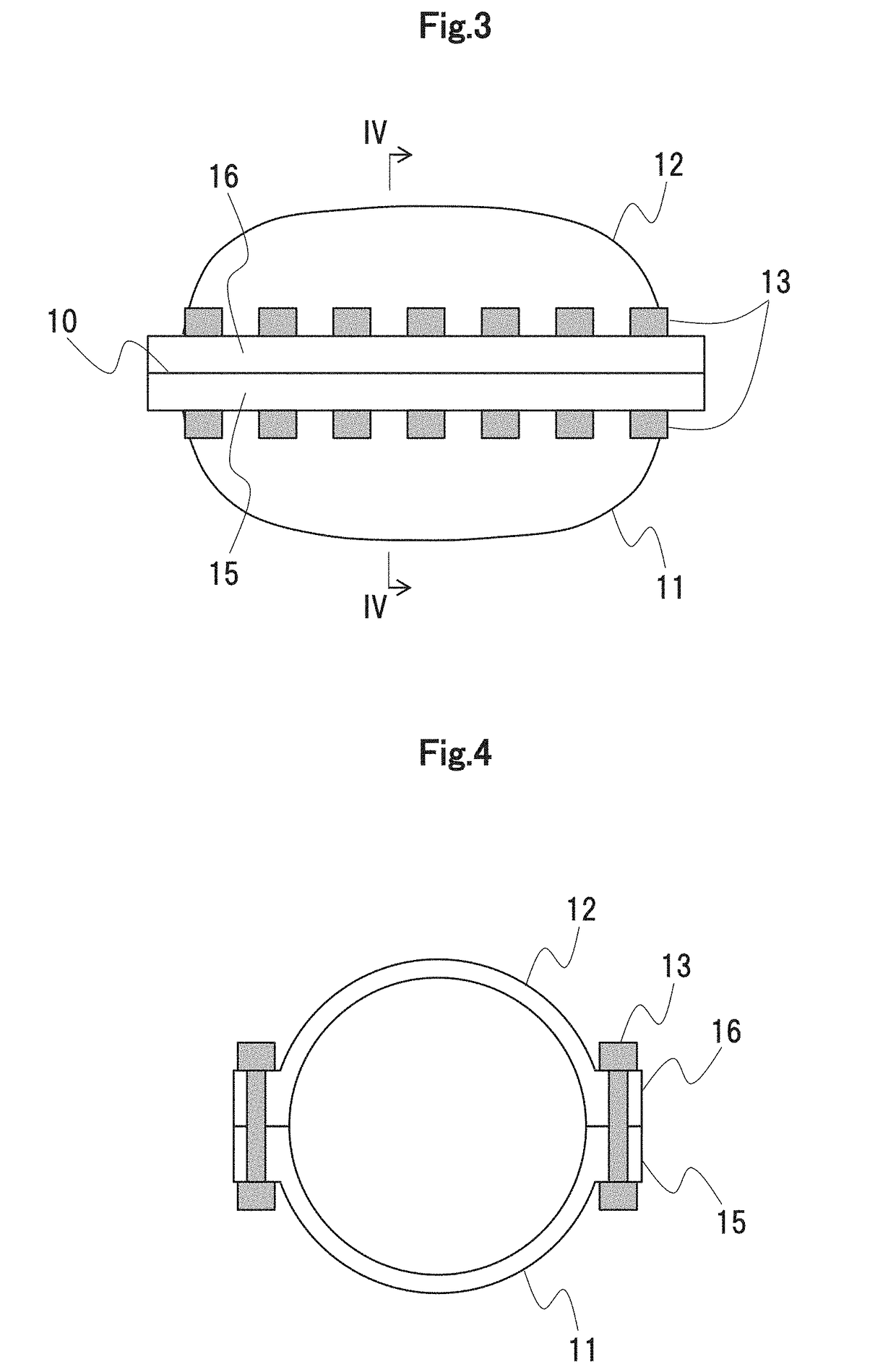
[0022]FIG. 1 is a perspective view of the lower half part of a steam turbine to which a method of assembling a turbine according to a first embodiment of the present invention is applicable, FIG. 2 is a longitudinal sectional view of the steam turbine to which the method of assembling a turbine according to the first embodiment of the present invention is applicable, FIG. 3 is a side view of an outer casing of the steam turbine to which the method of assembling a turbine according to the first embodiment of the present invention is applicable, and FIG. 4 is an arrow line sectional view taken along the arrow line IV-IV of FIG. 3.

[0023]As shown in FIGS. 1 and 2, a steam turbine 101 according to the present embodiment is equipped with an outer casing 1 supported by a foundation 100, an inner casing 2 accommodated in the outer casing 1, and a turbine rotor3 contained in the inner casing 2. The load of the turbine rotor 3 is supported, for example, by the foundati...

second embodiment

[0072]FIG. 9 is a flowchart illustrating the procedures of the assembling method according to the present embodiment. In FIG. 9, the steps that are the same as those of the flowchart shown in FIG. 6 are indicated by the same reference numerals, and a description thereof will be left out as appropriate. In the following, the assembling method of the present embodiment will be described.

[0073]The method of assembling a turbine according to the present embodiment differs from the turbine assembling method of the first embodiment in that there is further provided step P0. Otherwise, the turbine assembling method is the same as the turbine assembling method of the first embodiment.

Step P0

[0074]Measurement data on the configuration of the casing upper half part and the casing lower half part at the time of the manufacturing thereof is gained, and the gained measurement data on the configuration of the casing upper half part and the casing lower half part at the time of the manufacturing t...

third embodiment

[0079]FIG. 10 is a flowchart illustrating the procedures of the assembling method of the present embodiment. In FIG. 10, the steps that are the same as those of the flowchart shown in FIG. 9 are indicated by the same reference numerals, and a description thereof will be left out as appropriate. In the following, the assembling method of the present embodiment will be described.

[0080]The present embodiment is applicable when installing a steam turbine at the time of construction of an electric power plant equipped with a steam turbine. More specifically, the assembling method of the present embodiment differs from the assembling method of the second embodiment in that step B1a is provided instead of step B1 and that step P1a is provided instead of step P1. Otherwise, the assembling method is the same as the assembling method according to the second embodiment.

Step B1a

[0081]There are installed the outer casing lower half part 11, the inner casing lower half part 21, and the bearings....


PUM


Abstract

The invention is directed to maintaining the accuracy in the positional adjustment of a stationary part while shortening a turbine assembly period through the omission of the temporary assembly of a casing. A method of assembling includes gaining measurement data on the configuration of a casing upper half part not fastened to a casing lower half part; gaining measurement data on the configuration of the casing lower half part in an open state in which the casing upper half part and a rotor are removed and in which a stationary part is mounted; comparing measurement data on the configuration of the casing upper half part and the casing lower half part with simulation data on the configuration of the casing upper half part and the casing lower half part previously obtained to select simulation data closest to the measurement data on the configuration of the casing upper half part and the casing lower half part; calculating, based on the selected simulation data, a change amount of the configuration of the casing upper half part and the casing lower half part when the casing upper half part is fastened to the casing lower half part in the open state; and adjusting the installation position of the stationary part inside the casing taking into account the calculated change amount.

Description

BACKGROUND OF THE INVENTION1. Field of the Invention[0001]The present invention relates to a method of assembling a turbine, an assembly work supporting system, and a control program.2. Description of the Related Art[0002]Generally speaking, a casing of a turbine (the inner casing and the outer casing) is divided into a casing upper half part and a casing lower half part of the half-divided configuration, and flange portions of the casing upper half part and the casing lower half part are fastened to each other by bolts. Accommodated in the casing are diaphragms, etc. constituting a stationary part and a turbine rotor constituting a rotor rotating with respect to the stationary part.[0003]Between the rotor and the stationary part covering the rotor, there exists a clearance, through which part of steam (working fluid) can pass. The flow thus passing through the clearance between the rotor and the stationary part opposite the same is referred to as the “leakage flow” as appropriate i...

Claims


Application Information

Patent Timeline
Patent Type & Authority Applications(United States)
IPC IPC(8): G05B19/4097F01D25/24
CPCG05B19/4097F01D25/243F05D2220/31F05D2230/60F05D2240/14F05D2240/24G05B2219/35134G05B2219/32359G05B2219/45055G06F30/17G06F30/20F01D21/003F01D25/26F05D2260/81F01D25/285G01B21/32
Inventor YASHIRODAI, KENJIKODERA, JUICHIMIZUMI, SHUNSUKEISHIBASHI, KOJI
Owner MITSUBISHI POWER LTD
Why Eureka
Try Eureka