Tissue imaging system and method for tissue imaging

a tissue imaging and tissue technology, applied in the field of medical devices, can solve the problems of increasing the likelihood of inaccurate measurements, affecting the likelihood of errors, and inability to accurately and accurately image cancerous, necrotic or other diseased tissue, etc., to achieve convenient determination, convenient and accurate tissue imaging, and efficient

Pending Publication Date: 2018-10-25
BEST MEDICAL INT
View PDF3 Cites 49 Cited by
  • Summary
  • Abstract
  • Description
  • Claims
  • Application Information

AI Technical Summary

Benefits of technology

[0027]The method also includes fusion of the 3D volumes of the tissue contoured on the ultrasound image and the extracted tissue imaged via the x-ray subsystem by the fusion processor in the computer system. More specifically, overlaying one volume over the other for visual representation of the difference and performing quantitative analysis by determining / calculating the difference in volume, length, width and height of the two volumes, The visualization of 3D volumes overlaid on top of each other and the determined differences has the advantage of providing quantitative feedback on the error in specimen extraction facilitates preventing subjectivity in deciding on the amount of tissue to be extracted.
[0028]The method also includes performing biopsies under ultrasound guidance. The method enables marking of biopsy needles visualized in a 2D live ultrasound image and visualizing in a 3D ultrasound volume to provide an accurate representation of the angle and the position of the biopsy needle with respect to the structure being biopsied. In addition, the method provides the capability of visualizing all the biopsies performed on the tissue by displaying the needle paths of all biopsies in 2D and 3D ultrasound visualized on the user interface.

Problems solved by technology

The excising of cancerous, necrotic or other diseased tissue can, in some instances, be relatively complex, particularly to assure that the appropriate amount or volume of cancerous, necrotic or other diseased tissue, as typically also includes an amount of adjacent healthy tissue, is removed as an added precaution to minimize the re-occurrence or spreading in the body of the cancerous, necrotic or other diseased tissue.
However, traditional two dimensional (2D) X-ray imaging may be disadvantageous as typically involving a relatively long time period for analysis, as well as can likely increase the likelihood of inaccurate measurements, such as from movement of the tissue sample during X-ray imaging, and considering that it is typically performed under time constraints in relation to being performed during the time the person or animal is undergoing the surgical removal procedure.
Since the '193 Patent system appears to rely on human judgment in the determination of the sufficiency of tissue removed, and which judgment appears to be based only on the reconstructed images of the excised tissue, the likelihood of error can potentially still be affected by one or more of the human reviewer and / or the quality or accuracy of the reconstructed image of the excised tissue.
Further, it appears the '193 patent system image analysis does not provide a system and method for an image comparison of the excised tissue with that of the tissue to be removed as present in the body.
However, it appears the '405 patent system and method likewise does not specifically disclose a tissue imaging system and method for an image comparison of excised tissue from a body with that of the tissue to be removed as present in the body.
However, it appears the '227 patent system and method, as well as the above referred to systems that have been employed to track the position and orientation of an object, such as in medical applications, likewise do not specifically disclose a tissue imaging system and method for an image comparison of excised tissue from a body with that of the tissue to be removed as present in the body.

Method used


Image

  • Tissue imaging system and method for tissue imaging
  • Tissue imaging system and method for tissue imaging
  • Tissue imaging system and method for tissue imaging

Examples


Embodiment Construction

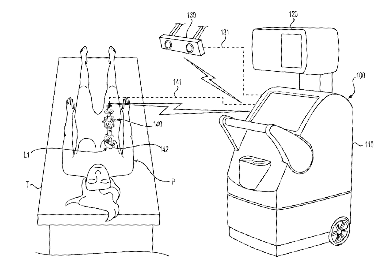
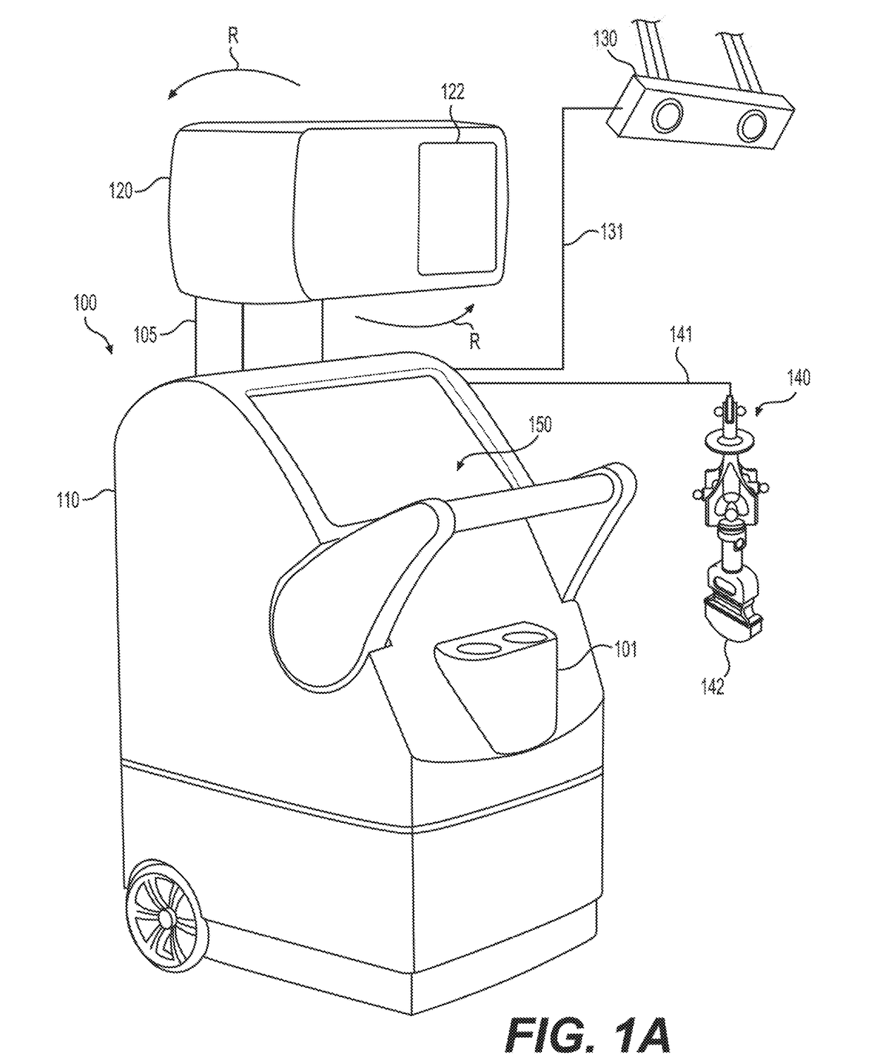
[0059]Referring now to FIG. 1A, there is illustrated a tissue imaging system 100. The system 100 includes a main body 110, an X-Ray Chamber 120, a neck 105, an interface display 150, and an Infrared 3D Imaging Camera 130. The neck 105 connects the X-Ray Chamber 120 with the main body 110. The neck 105 also provides a support / anchor for the X-Ray Chamber 120 to rotate in the arrowed direction R about its central axis. The ultrasound probe with tracker system 140 includes or incorporates an ultrasound probe 142. Also, the imaging system 100 can include a holder 101 that can house an ultrasound probe and an ultrasound gel or other items for the imaging procedure, for example.

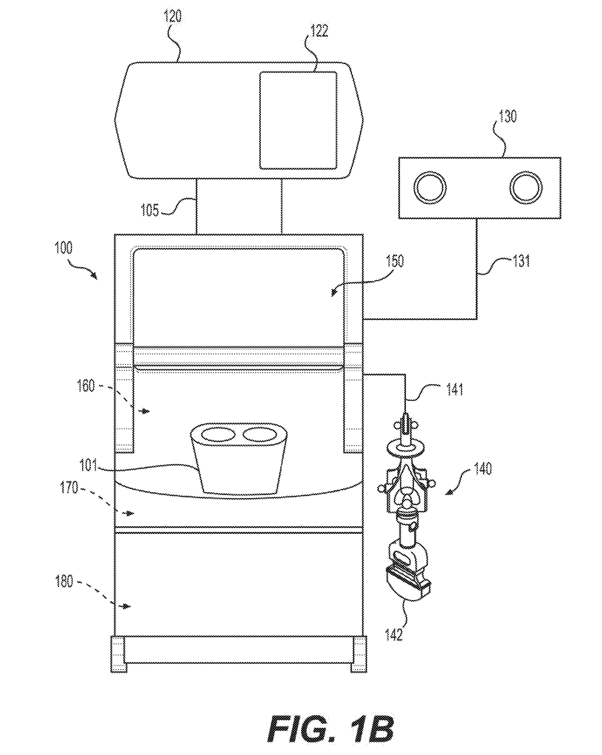
[0060]Referring to FIG. 1B, there is schematically illustrated the main body 110 that includes an X-Ray Generator, to be described, within the X-Ray Chamber 120, an X-ray controller system 160 for controlling various operations of the X-ray imaging generation and processing in the imaging system 100, an ultrasound ...


PUM

PropertyMeasurementUnit
distanceaaaaaaaaaa
rotational angleaaaaaaaaaa
angular rotationaaaaaaaaaa

Abstract

The tissue imaging system, incorporates an integrated X-Ray and Ultrasound Imaging system. The X-Ray system is used for imaging and generating a 3D Volume of the extracted tissue sample (specimen). The Ultrasound imaging system is used for imaging the body area of interest of the patient from which the tissue sample is to be extracted. On the display of the system, the physician draws contours on the area of interest and the same is displayed as a 3D Volume. A 3D volume of the extracted tissue is generated using the x-ray imaging sub-system. Quantitative analysis is performed on the two 3D volumes (extracted tumor x-ray imaging and the contoured ultrasound imaging) to determine the difference between the contoured and the surgically extracted specimen to assist the physician in determining if further surgical intervention is required.

Description

CROSS REFERENCE TO RELATED APPLICATION[0001]This application claims priority under 35 U.S.C. § 119 to U.S. Provisional Patent Application No. 62 / 490,021, filed on Apr. 25, 2017, hereby incorporated herein by reference in its entirety.FIELD OF THE INVENTION[0002]The invention generally relates to the field of medical devices, and more particularly to tissue imaging devices, systems and methods utilizing both ultrasound imaging and X-ray imaging in the removal of cancerous, necrotic or other diseased tissue from a body, such as from a human body, animal body or reptilian body, and generating three dimensional (3D) ultrasound images and 3D X-ray images of tissue prior to and after its removal from the body to determine whether the desired amount or volume of the cancerous, necrotic or other diseased tissue has been removed from the body.BACKGROUND[0003]Imaging devices, such as using ultrasound imaging or X-ray imaging, are commonly used in diagnosis for treatment of various medical iss...

Claims


Application Information

Patent Timeline
Patent Type & Authority Applications(United States)
IPC IPC(8): G06T7/62A61B8/08A61B8/00G06T7/00A61N5/10A61B10/04A61B34/10G01N23/046G01N29/44
CPCG06T7/62A61B8/483A61B8/0841A61B8/466A61B8/463A61B8/4254G06T7/0014A61N5/1007A61B10/04A61B34/10G01N23/046G01N29/44G06T2207/10116G06T2207/10136G06T2207/20221G06T2207/30096A61N2005/1024A61B2010/045A61B2034/107G01N2291/02475A61N5/1049A61N2005/1058A61B6/025A61B6/12A61B6/4233A61B6/466A61B6/502A61B6/5205A61B6/5247A61B8/0825A61B8/4444A61B8/5261A61B10/0233
Inventor GUPTA, VINEET
Owner BEST MEDICAL INT
Why Eureka
Try Eureka