Rotational wave nozzle

a technology of rotating wave and nozzle, which is applied in the direction of movable spraying apparatus, cleaning process and apparatus, chemistry apparatus and process, etc., can solve the problems of difficult to efficiently spray off liquid droplets, degrade drying quality, and poor drying quality, and achieves easy rotation, increase in rotation number, and high rotation number

Inactive Publication Date: 2018-11-01
FUJI ELECTRIC CO LTD
View PDF0 Cites 2 Cited by
  • Summary
  • Abstract
  • Description
  • Claims
  • Application Information

AI Technical Summary

Benefits of technology

[0011]However, the rotary shaft of the rotational wave nozzle is supported by the bearings so as to be freely rotatable and can easily rotate even due to low-pressure compressed air, which makes it easy for the number of rotations to increase. There is a problem in that a high number of rotations can worsen drying quality. Namely, as shown in FIG. 13, there is a relationship between the number of rotations of the rotational wave nozzle and drying quality, and when the number of rotations exceeds the optimal value, it becomes difficult to efficiently spray off the liquid droplets. In other words, until the number of rotations reaches the optimal valu

Problems solved by technology

There is a problem in that a high number of rotations can worsen drying quality.
Namely, as shown in FIG. 13, there is a relationship between the number of rotations of the rotational wave nozzle and drying quality, and when the number of rotations exceeds the optimal value, it becomes

Method used


Image

  • Rotational wave nozzle
  • Rotational wave nozzle
  • Rotational wave nozzle

Examples


embodiment 1

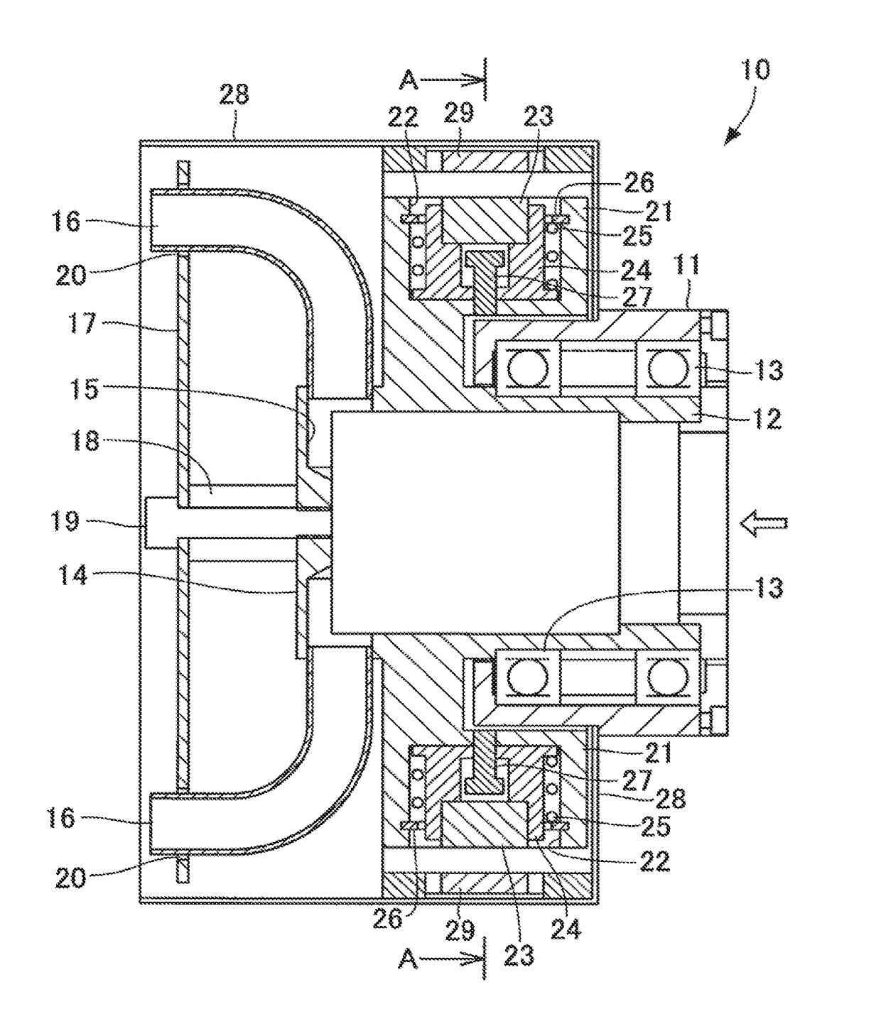
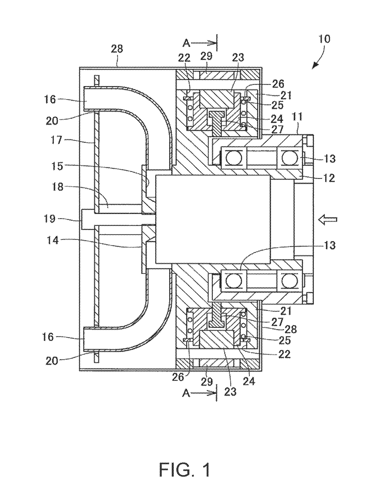
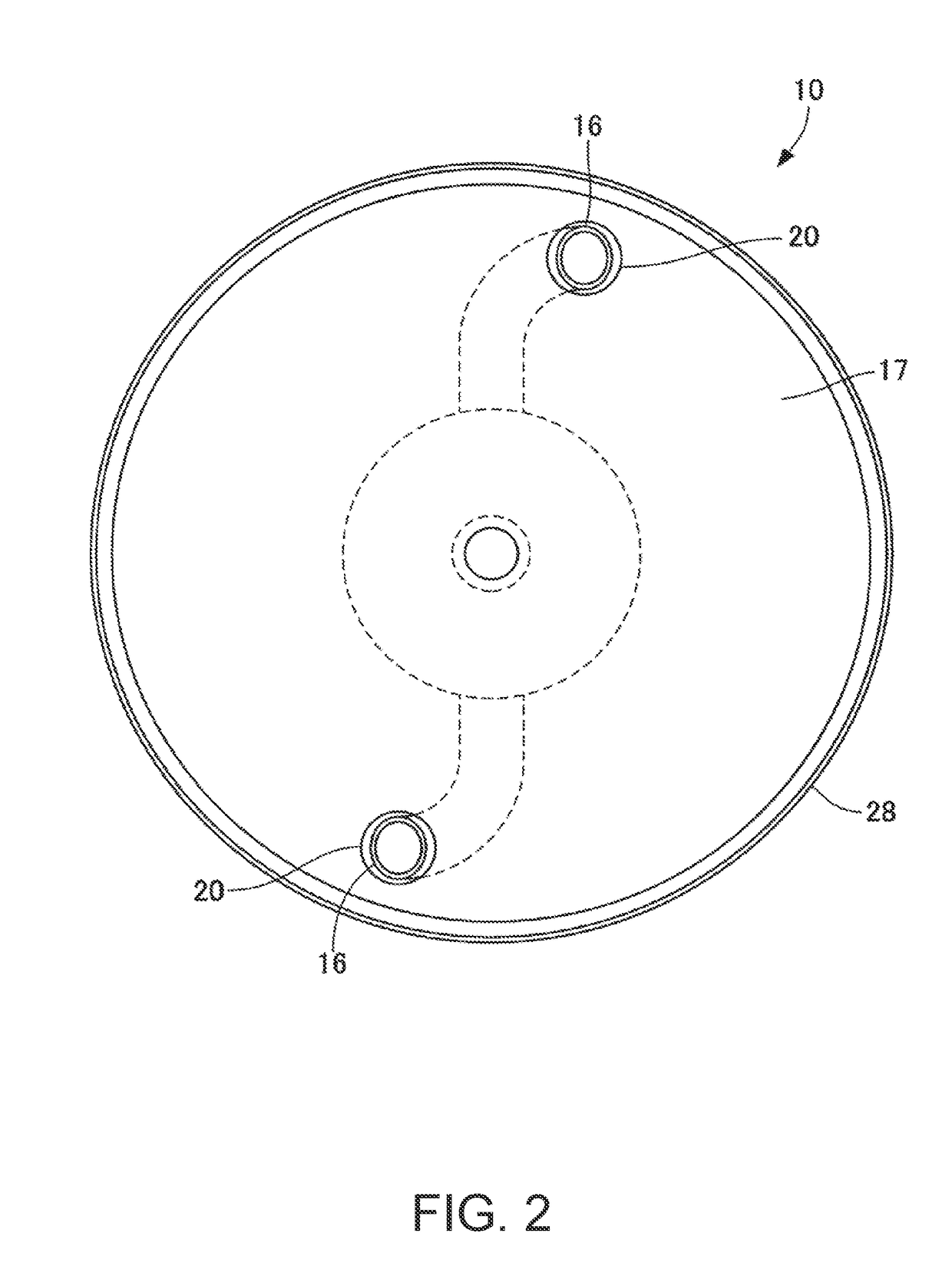
[0032]FIG. 1 is a cross-sectional view of a rotational wave nozzle of Embodiment 1. FIG. 2 is a side view of the rotational wave nozzle seen from the side of the spray nozzle. FIG. 3 is a cross-sectional view along the arrow A-A in FIG. 1 and shows the rotational wave nozzle while stopped. FIG. 4 is a cross-sectional view along the arrow A-A in FIG. 1 and shows the rotational wave nozzle while operational.

[0033]As shown in FIG. 1, a rotational wave nozzle 10 of Embodiment 1 has a hollow cylindrical fixed housing 11. The fixed housing 11 has a hollow cylindrical rotary cylinder 12 disposed concentrically therein, and the rotary cylinder 12 is supported by two bearings 13 installed inside the fixed housing 11 separated in the axial direction such that the rotary cylinder can rotate freely.

[0034]One end of the rotary cylinder 12 is open, and the other end is closed by a closing member 14 formed integrally with the rotary cylinder. Pipe joint parts 15 are formed on the rotary cylinder 1...

embodiment 2

[0050]FIG. 5 is a side view of a rotational wave nozzle of Embodiment 2 as seen from the side of the spray nozzle. FIG. 6 is a cross-sectional view along the arrow B-B in FIG. 5 and shows the rotational wave nozzle of Embodiment 2. FIG. 7 is a cross-sectional view along the arrow C-C in FIG. 5 and shows the rotational wave nozzle of Embodiment 2 while stopped. FIG. 8 is a cross-sectional view along the arrow D-D in FIG. 7 and shows the rotational wave nozzle of Embodiment 2 while stopped. FIG. 9 is a cross-sectional view along the arrow C-C in FIG. 5 and shows the rotational wave nozzle of Embodiment 2 while operational. FIG. 10 is a cross-sectional view along the arrow E-E in FIG. 9 and shows the rotational wave nozzle of Embodiment 2 while operational. In FIG. 5 to FIG. 10, the constituent components that are the same as the constituent components shown in FIG. 1 to FIG. 4 are given the same reference characters and detailed explanations thereof will be omitted. Accordingly, in th...


PUM


Abstract

A rotational wave nozzle includes a fixed housing having a hollow cylindrical shape; a rotary cylinder inside the fixed housing such that the rotary cylinder is freely rotatable about the axial direction; a spray nozzle fixed on a front side of the rotary cylinder, emitting a compressed gas received by a rear end of the rotary cylinder outwardly, an emission direction of the spray nozzle being inclined relative to the axial direction of the rotary cylinder so that the emitted compressed gas causes the rotary cylinder and the spray nozzle fixed thereto to rotate; and a rotation suppressor fixed on a circumference side of the rotary cylinder, the rotation suppressor having a movable member that moves outwardly in a radial direction in response to a centrifugal force such that the movable member causes the rotation of the rotary cylinder due to the emitted compressed gas to be braked.

Description

BACKGROUND OF THE INVENTIONTechnical Field[0001]The present invention relates to a rotational wave nozzle that intermittently sprays a fluid onto a workpiece.Background Art[0002]As a device for spraying fluid onto a workpiece, an air gun is known which ejects compressed air and sprays the ejected compressed air onto a wet-washed workpiece, thus drying the workpiece by removing liquid droplets. This type of air gun is also used in the process for delivering semiconductor chips. Namely, in the process for delivering a semiconductor chip, the tray that transports and protects the semiconductor chips to be delivered is washed with warm water, and then compressed air is sprayed onto the wet tray with the air gun in order to spray off the liquid droplets, after which the tray is put into a drying furnace and dried.[0003]In the spray drying method using the air gun, phenomena can be observed in which the liquid droplets run on the surface of the tray, go around to the back surface of the t...

Claims


Application Information

Patent Timeline
IPC IPC(8): B05B3/00B05B3/06
CPCB05B3/003B05B3/06B05B1/005B05B3/02B08B5/02
Inventor SHIMIZU, HITOSHI
Owner FUJI ELECTRIC CO LTD
Why Eureka
Try Eureka