Housing for turbocharger and method for manufacturing the same

a turbocharger and housing technology, applied in the direction of machines/engines, stators, liquid fuel engines, etc., can solve the problems of reducing the compression efficiency of supplied air, increasing manufacturing costs, and reducing the workability of assembling, so as to reduce the parts count, facilitate formation, and improve the effect of assembling workability

Active Publication Date: 2018-11-01
OTICS CORP
View PDF8 Cites 5 Cited by
  • Summary
  • Abstract
  • Description
  • Claims
  • Application Information

AI Technical Summary

Benefits of technology

[0025]According to the aforementioned one aspect, the housing for a turbocharger is dividably formed, and the refrigerant flow path is defined by the first flow-path formation part and the second flow-path formation part. The first flow-path formation part and the second flow-path formation part are formed respectively at each opposing part of the scroll piece and the shroud piece which oppose each other. The refrigerant flow path is sealed at an inner circumferential seal part on the inner circumferential side of the refrigerant flow path and at an outer circumferential seal part on the outer circumferential side of the refrigerant flow path. The inner circumferential seal part is formed by press-fitting the first press-fitting portion of the shroud piece into the first press-fitted portion of the scroll piece, and the outer circumferential seal part is formed by press-fitting the second press-fitting portion of the shroud piece into a second press-fitted portion of the scroll piece. Such a configuration makes it possible to seal the ref...

Problems solved by technology

Thus, parts count is indispensably increased, which causes increase in manufacturing cost and reduction in assembling workability.
Because the cross-sectional shape of the scroll chamber largely differs from a circle accordingly, reduction in compression efficiency of supplied air is caused.
On the other hand, this method ...

Method used


Image

  • Housing for turbocharger and method for manufacturing the same
  • Housing for turbocharger and method for manufacturing the same
  • Housing for turbocharger and method for manufacturing the same

Examples


embodiments

Embodiment 1

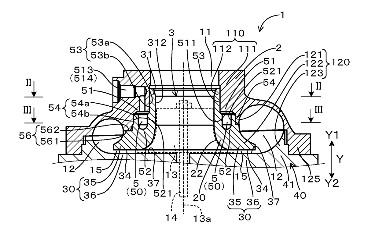
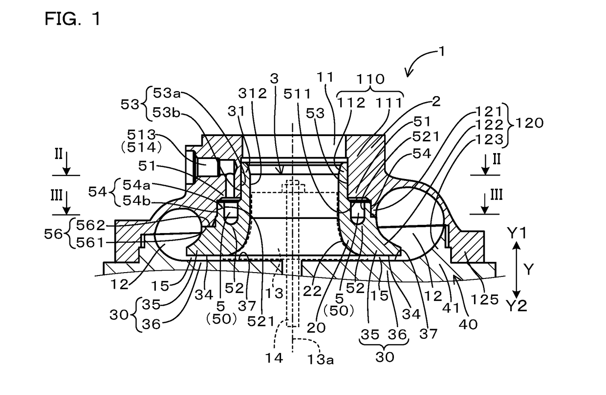
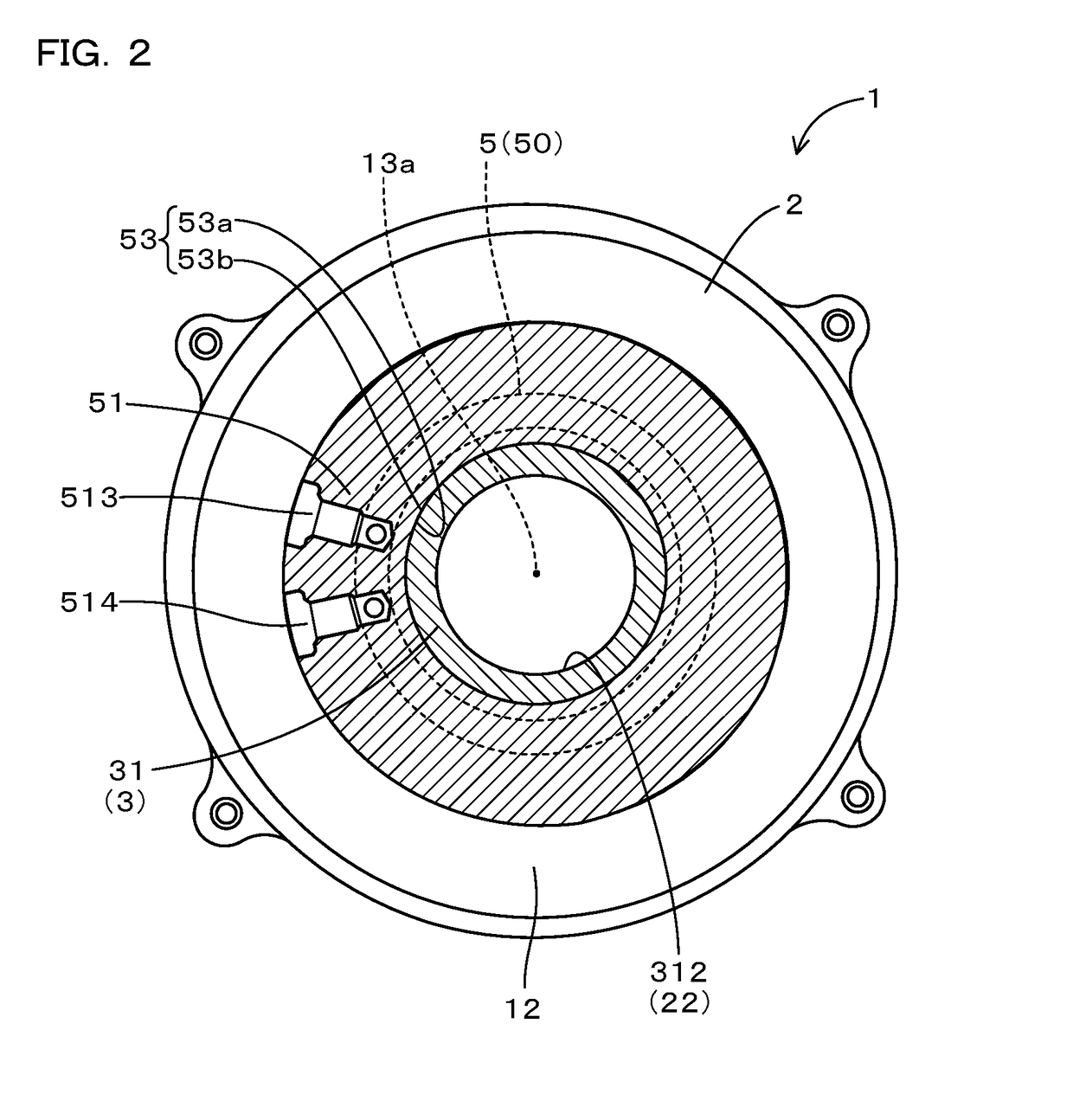
[0054]Hereinafter, an embodiment of the aforementioned housing for a turbocharger will be described with reference to FIGS. 1 to 9.

[0055]As shown in FIG. 1, a housing 1 for a turbocharger houses a compressor impeller 13, and is provided with an intake port formation part 110, a shroud part 20, a diffuser part 30, a scroll chamber formation part 120 and a refrigerant flow path 5.

[0056]The intake port formation part 110 forms an intake port 11 configured to suck in air toward the compressor impeller 13.

[0057]The shroud part 20 surrounds the compressor impeller 13 in the circumferential direction and has a shroud surface 22 facing the compressor impeller 13.

[0058]The diffuser part 30 is formed on the outer peripheral side of the compressor impeller 13 in the circumferential direction and forms a diffuser passage 15 that allows compressed air discharged from the compressor impeller 13 to pass therethrough.

[0059]The scroll chamber formation part 120 forms a scroll chamber 12 ...

embodiment 2

[0103]In the housing for a turbocharger 1 according to the present embodiment, as shown in FIGS. 15 and 16, the refrigerant flow path 5 includes a cut part 57. Note that components equivalent to those in Embodiment 1 are allotted with the same reference numerals to simplify the description.

[0104]The method for manufacturing the housing 1 for a turbocharger according to the present embodiment will be described below. As shown in FIG. 17, the molding step S1 is performed first similarly in Embodiment 1. Then, a cutting step S2 is performed as follows. The bottom of the second wall surface 521 formed from the second flow-path formation part 52, which is recessively formed toward the Y2 side, that is part of the second wall surface 521 positioned most forward on the Y2 side is cut to form the second flow-path formation part 52 into a further recessed shape. After the cutting step S3, the assembling step S2 is performed similarly in Embodiment 1.

[0105]When the second flow-path formation ...


PUM


Abstract

A housing for a turbocharger, which makes it possible to prevent sticking of deposit and attain satisfactory assembling workability and easy moldability by die casting. The housing is dividably composed of a scroll piece and a shroud piece, including an annular refrigerant flow path defined by a first flow path formation part of the scroll piece and a second flow path formation part of the shroud piece. The first and second flow path formation parts are fitted with each other at inner and outer circumferential seal parts for sealing the refrigerant flow path on inner and outer circumferential sides thereof. The inner circumferential seal part is formed by press-fitting a first press-fitting portion of the shroud piece into a first press-fitted portion of the scroll piece. The outer circumferential seal part is formed by press-fitting a second press-fitting portion of the shroud piece into a second press-fitted portion of the scroll piece.

Description

CROSS-REFERENCE TO RELATED APPLICATION[0001]The present application claims priority under 35 U.S.C. í 119 to Japanese Application No. 2017-088189, filed on Apr. 27, 2017, entitled “HOUSING FOR TURBOCHARGER AND METHOD FOR MANUFACTURING THE SAME”. The contents of this application are incorporated herein by reference in their entirety.BACKGROUND OF THE INVENTIONField of the Invention[0002]The present invention relates to a housing for a turbocharger and a method for manufacturing the same.Description of the Related Art[0003]A turbocharger to be mounted on an internal combustion engine of an automobile or the like includes a compressor impeller and a turbine impeller, which are housed in a housing. The compressor impeller is disposed in an air flow path that is formed inside of the housing. The air flow path is provided with an intake port for sucking in air toward the compressor impeller, a diffuser passage through which compressed air discharged from the compressor impeller passes thr...

Claims


Application Information

Patent Timeline
IPC IPC(8): F04D29/44F01D9/02F04D29/42F04D29/58
CPCF04D29/441F01D9/026F04D29/4213F04D29/584F05D2220/40F05D2230/21F04D29/4206F05D2260/20F05D2260/37F05D2260/607F01D25/24
Inventor NIWA, TETSUYAISOGAI, TOMOYUKI
Owner OTICS CORP
Why Eureka
Try Eureka